2-35
Drive Offsets Calibration
iControl AC
2
2. Follow the on-screen instructions, “To perform the drive offsets calibration...” (cali-
brates Input ADC and Output DAC offset).
3. Once calibration is Done, the offset values shown on the Setup > Drive tab should match
those shown on the Drive Configuration tab (Configuration > Drive > Calibration tab).
Manual Drive Setup Procedure
MCE recommends first performing the Automated Drive Setup Procedure previously described
and then verifying the most critical offsets (Output DAC and Input ADC - Tachometer)
using the manual procedure. If the automated procedure is unsuccessful, the manual procedure
must be used.
Before adjusting the drive, verify that:
• the CONTROLLER STOP switch is in the RUN position
• the iBox Safety OK LED is ON
• the iBox Door Locked LED is ON
• the iBox Fault LED is OFF
• iView is connected, write privilege has been obtained (Write Privilege > Acquire
selected and “Yes” softkey on iBox pressed in response)
1. Verify Pattern scaling is set to 100% (Configuration > Pattern > Common tab).
2. On iView, display the Drive - Offsets tab (Configuration > Drive > Calibration tab).
3. Output DAC: With zero speed commanded (car idle):
• TORQMAX F5: verify that pattern voltage applied to the AC drive unit reads 0.0 volts
between F5 drive terminals X2A-1 (+) and X2A-2 (—).
• Magnetek: verify that the D1 Speed Command value is zero). If not, adjust Output DAC
on the Drive/Calibration screen by entering and sending small negative or positive val-
ues until the reading is as close to 0.0 volts as possible (less than 1mV). The DAC
adjustment range is from —0.25 to +0.25 units.
4. On iView, display the Drive - Offsets tab (Configuration > Drive > Calibration tab). Also
display the Virtual Oscilloscope (View > Virtual Oscilloscope) and set Test point 1 =
Tachometer Signal.
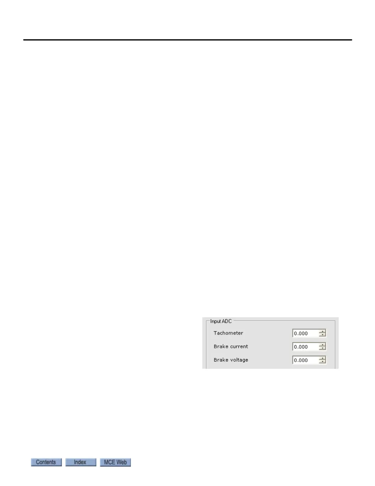
5. Input ADC - Tachometer: Adjust the
Input ADC - Tachometer parameter by
entering and sending small negative or
positive values until the Test point 1
value is as close to 0.0 as possible
(20mV). The ADC adjustment range is
from —0.5 to +0.5.
6. Input ADC - Brake current: Set Virtual Oscilloscope Test Point 1 = Brake Current Feed-
back and adjust the Input ADC - Brake current parameter by entering and sending small
negative or positive values until the Test point 1 value is as close to 0.0 as possible.
7. Input ADC - Brake voltage: Set Virtual Oscilloscope Test Point 1 = Brake Voltage Feed-
back and adjust the Input ADC - Brake voltage parameter by entering and sending small
negative or positive values until the Test point 1 value is as close to 0.0 as possible.