3-3
Installing iLink
iControl AC
3
Installing iLink
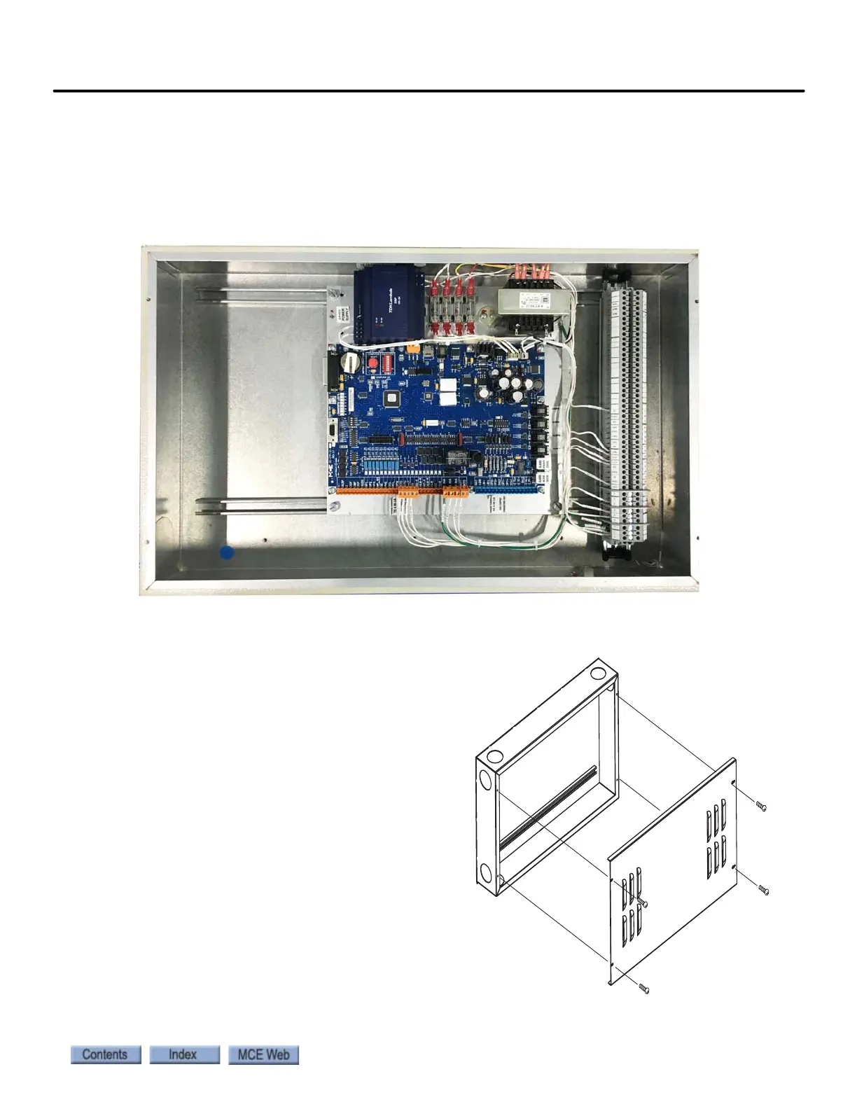
iLink is the cartop interconnect box used with iControl systems. The illustration below shows a
view of iLink circuitry with the cover removed. Make connections to the interconnect box as
shown in your job prints.
Figure 3.1 iLink Circuitry and Wiring
Installing the iLink Enclosure
The iLink enclosure is typically mounted on the
left side (as you face the car) of the cartop,
opposite the iLand system. The enclosure has
several partially-punched knockouts to accom-
modate two-inch conduit connections. Mount
the iLink enclosure on or between the cross-
head beams.
Vertical mounting as shown, is preferred.
Mounting the iLink horizontally is acceptable
only if it is well protected from metal filings or
other debris that might accumulate and dam-
age electrical components. The dimensions of
the iLink enclosure depend upon how many
input and/or output boards are required for a
particular job.