5-39
Load Weighers
iControl AC
5
Load Weighers
Please see the installation instructions shipped with the selected load weigher.
Weigher Calibration with iControl
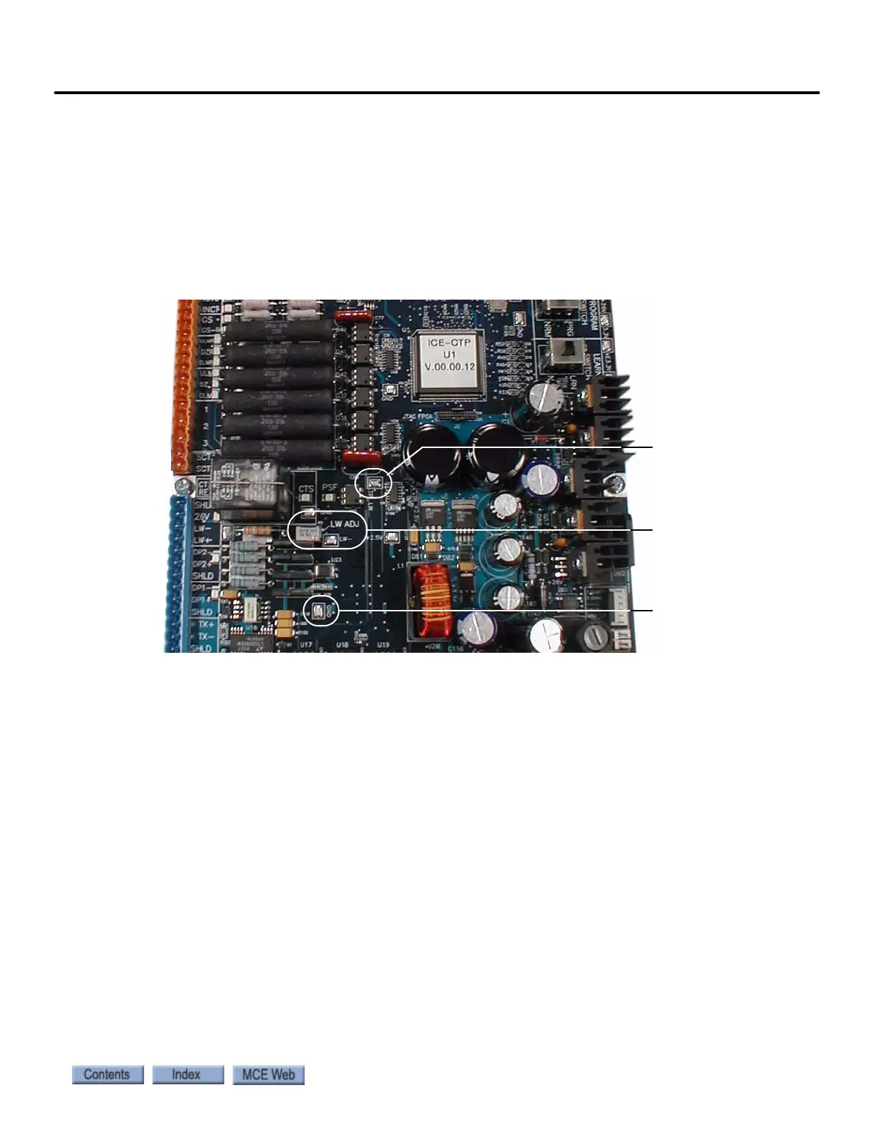
1. Connect a multimeter to test points TP_LW and GND on the ICE-CTP board in the
cartop Box. Adjust trimpot LW ADJ until the meter reads the same value noted in step
6 in the calibration procedure.
Figure 6. ICE-CTP Cartop Processor Board
2. To view load weigher voltages using the iView Virtual Oscilloscope:
• Connect to the controller; display the Virtual Oscilloscope (View > Virtual Oscillo-
scope)
• Select Load Weigher (Raw) for Test point 1
•Observe Load Weigher voltage values on the digital display.
3. To verify the linearity of the load weigher, place weights in the car that represent the fol-
lowing and observe the voltage values:
• Empty car - about 0.0 volts
• 25% of overload weight - about 2.5 volts
• 50% of overload weight - about 5.0 volts
• 75% of overload - about 7.5 volts
• Full load weight - about 8 volts
• Overload weight - about 10 volts
4. On the iView Controller > Configuration > Load Weigher tab:
•Set Load weighing device type to Analog signal.
• Set Sensing type to Cross head deflection or rope tension sensing.
TP_LW test point
LW ADJ trim pot
GND test point