2-13
Basic Safety String and Associated Wiring
iControl AC
2
Temporary CTS Relay Bypass
Because the iLink cartop interconnect box which contains the Cartop Safety (CTS) Relay is not
yet installed, it is necessary to bypass the CTS relay temporarily (for Construction Mode only).
(If you in fact are installing the iLink cartop box already, please refer to the iLink instructions in
Section 3 of this guide.)
1. Refer to the job prints.
2. Connect the safety string in series between the iBox SAFH and SAFC terminals.
3. You must provide an Emergency Stop switch in series between SAFH and SAFC.
Make sure the Emergency Stop switch is wired in series between SAFH and SAFC to allow emergency
stopping while working on the cartop.
Access Locks and Contacts
1. Refer to the job prints.
2. Connect the switches for front and rear (if present) doors as shown.
Rope Gripper Wiring
An “emergency brake” may be connected between iControl terminals RG1 and RG2 to stop
unexpected car motion. After it is triggered, press the iBox Fault Reset button or the Rope Grip-
per board reset button to reset the rope gripper.
1. Refer to the job prints (MRW- machine room wiring sheets).
2. Connect the rope gripper to iControl RG1, RG2, RG5, and RG7 terminals as shown.
Temporary Rope Gripper Bypass
If a Rope Gripper will be installed later, you may temporarily bypass the input by installing a
jumper between RG5 and RG7.
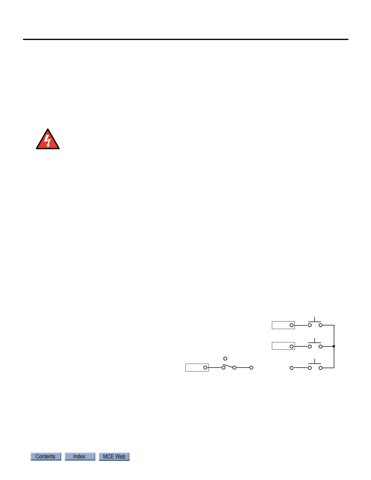
Temporary Cartop Inspection Wiring
Four cartop switches control car motion:
An Inspection Enable switch, a Safe switch,
an Up switch, and a Down switch.
1. Refer to job print drawing -CW,
Cartop Inspection Station.
2. Connect the (Normally Closed) Car-
top Inspection Enable switch
between the #3 bus and the iCon-
trol INCT terminal as shown. (This
is the switch used to put the controller on cartop inspection. INCT is active low.)
3. Connect a Safe push button switch between the #3 bus and the direction push buttons.
4. Connect a Down push button switch between the Safe switch and the iControl ICTD ter-
minal as shown (active high).
5. Connect an Up push button switch between the Safe switch and the iControl ICTU ter-
minal as shown (active high).
ICTD
ICTU
3
3
DOWN
INCT
INSPECTION
SAFE
UP
Insp
Norm