5-27
Serial Hall Call
iControl AC
5
General Check
1. Check all power and data cable connections.
• Port status LED on System hub/switch should light when the Ethernet cable is plugged
in between the hub/switch and the serial/Ethernet board.
• Ribbon cable (if used) seated properly on the hall call driver and the serial/Ethernet
board.
• Use a voltmeter to measure between each of the three DC voltages (3.3V, 5V, 9V) on
the serial/Ethernet (SC-HCE) board to ground. Voltages should read the provided
level, +/- 10%.
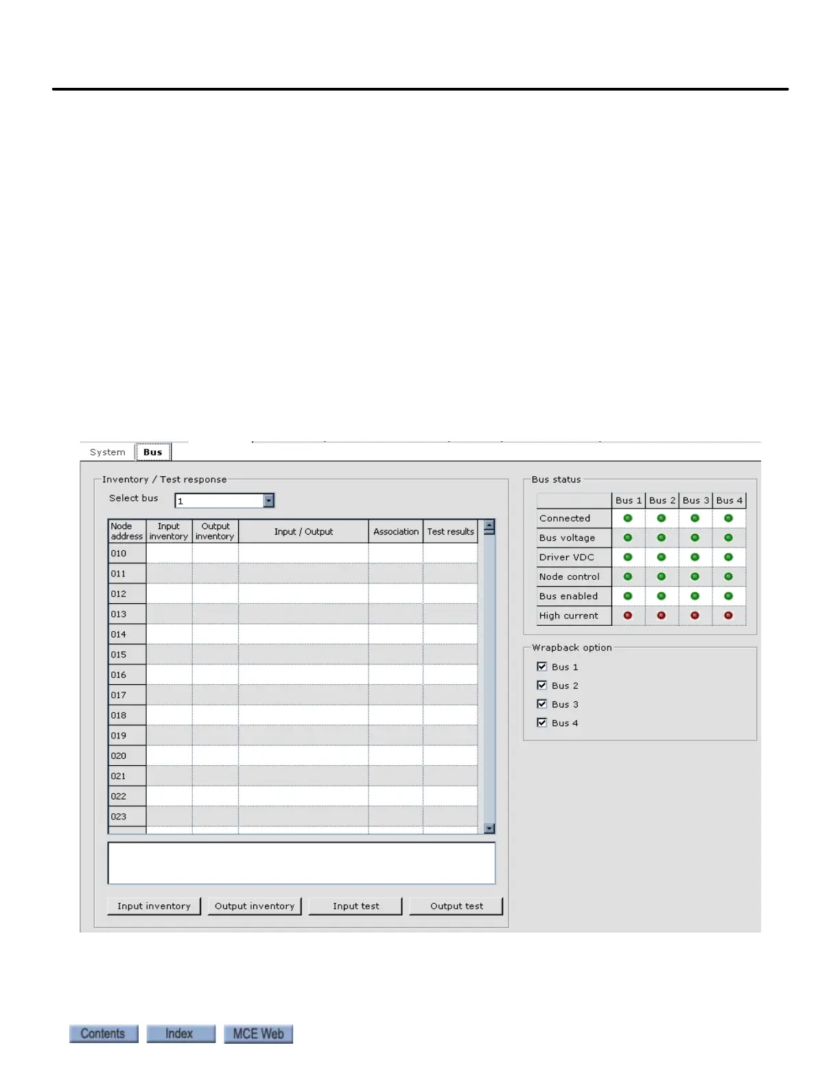
iView Check Use the iView System I/O Configuration screen, Bus tab to see if trouble is
indicated and to check that hall calls are addressed as specified in your job prints.
1. Launch iView and connect to the group.
2. Open the System I/O Configuration screen and select the Bus tab.
3. Verify the state of the indicator LEDs and that the addresses are as defined in the group
job prints (inputs as expected per serial address and Labels mapped to correct floor).