6-81
Replacing Circuit Boards
iControl AC
6
iBox Installation
1. Verify that power is off at the main disconnect. Open the iControl cabinet.
2. Remove the cover (bezel) from the new iBox.
3. Secure the new iBox in position between the rail-mounted circuit boards.
4. Slide the rail-mounted circuit boards above and below the iBox back into position so
that the central bus is plugged back in.
5. Tighten the retaining screws for the iBox and all of the circuit boards.
6. Reinstall the iBox cover.
7. Reconnect all cabling to the body of the iBox.
iBox Configuration > Load
While online (connected to a controller, you may select a Configuration (.cfg) file and send all or
selected data from that file to the controller. Please refer to “Loading Parameters from a Config-
uration File” on page 8-22.
Replacing Circuit Boards
Peripheral circuit boards in iControl and in the iLink cartop box are connected along a central,
pluggable bus. The boards are mounted on slide-tracks so that, if you need to replace a board
you can loosen the mounting bolts of the boards above or below it, slide them away, then
loosen, slide, and remove the board you need to replace. In iControl, the central bus extends
both above and below the iBox.
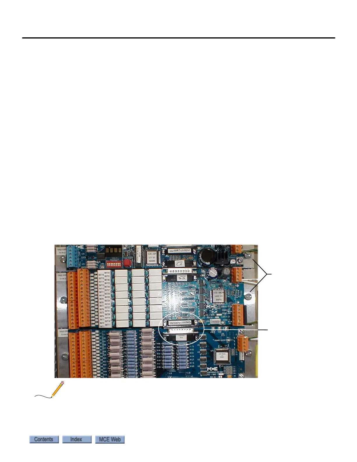
Figure 6.1 Circuit Board Removal and Replacement
Before using iView to assign or reassign inputs or outputs to I/O boards, consult MCE so that your job
prints can be corrected. Remember that reassigning an input or output will also require appropriate re-
routing of the wiring.
Board retaining
screws: Loosen to
slide board
Pluggable central
bus connectors