6-98 Manual # 42-02-2223
Troubleshooting
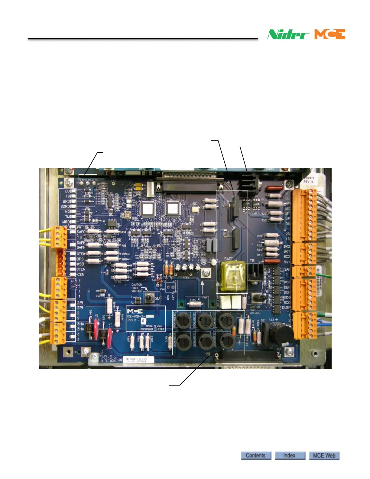
ICE-IRB Relay Board
The Relay Board is an integral part of the iBox. Three system relays are mounted on the board.
The SAFT relay is socketed (replaceable). There are also six fuses protecting the 110VDC and
120VAC iBox output buses that may be replaced. Electrically, the Relay Board is between the
iBox processor and the motor and brake field modules inside the iPower Box. The SB and 3 ter-
minals are accessible through the front of the iBox and bypass the safety string when “jump-
ered” together. If a jumper is placed, it “times out” automatically after 15 minutes. In TSSA
jurisdictions, SB and 3 terminals are capped with insulators and are not front panel accessible.
Figure 6.8 ICE-IRB Relay Board
Power Bus Fuses
250VAC,
Bussman MDQ or
Littelfuse Type 313
Motor Driver Relay
Brake Driver Relay
Safety Relay
Testpoints:
3.3V, 5.0V, 15V
TM Triac