6-114 Manual # 42-02-2223
Troubleshooting
SC-HCDA-ISO Serial Driver Isolation Board
The SC-HCDA-ISO Serial Hall Call Driver Isolation Board is placed between the SC-HCDA
Serial Hall Call Driver (usually mounted inside the iPower Box) and the Serial Hall Call Input
on the right side of the iBox. Revision 6.0 and later ICE-IMP boards incorporates the isolation
circuitry, eliminating the need for the SC-HCDA-ISO. Please refer to “Serial Hall Call” on
page 5-17 for additional information.
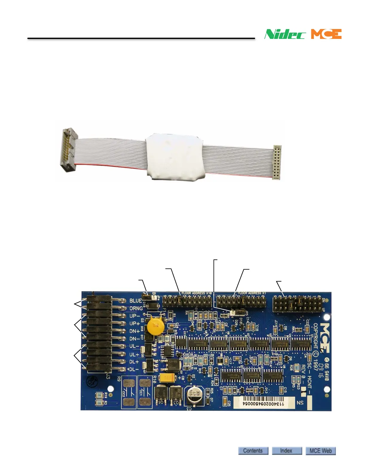
Figure 6.16 SC-HCDA-ISO Serial Hall Call Driver Isolation Board
SC-HCNT Serial Hall Call Node Board
In a typical installation, an SC-HCNT Serial Hall Call Node board is mounted in each hall call
enclosure. Please refer to “Hall Call Installation” on page 5-19. The board provides two outputs
to power hall call lamps or LEDs, two inputs for hall call buttons, and jumpers to set floor ID
and hall call “type”.
Figure 6.17 SC-HCNT Serial Hall Call Node Board
For more information on setting the node board addresses, see “Setting Node Board Addresses”
on page 5-20.
JP1 Call Type
JP2 Floor Address X1
JP3 Floor Address X10
JP4 unused
Hall Call Bus
Power / signal
Up / Down
buttons
Up / Down
indicators
JP5 Future use