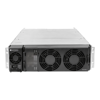
GTR8000BaseRadio
3.4.2.1HowtoMounttheBaseRadio/Receiver
ProcedureSteps
1Determinewhereontherackyouwillmountthedeviceandmarkthelocation.Thebracketsareusefulin
makingthisdetermination,andthepinonthebackofthebrackethelpsinndingtheexactlocationontherack.
2Attachthebracketstothesidesofthechassis:
a.UseM6x1x13machinescrewswithacaptivewasher(zincplated).
b.Screwonebracketintotheclinchnutsonthesideofthechassis.
c.Screwthesecondbracketitintotheclinchnutsontheothersideofthechassis.
3Liftthebaseradio/receiverintoplaceontherackusingthepinsonthebracketstoproperlylineupthedevice.
4Attachthetwobracketstotherack:
a.ForaMotorolamodularrack,useM6x1x10threadformingscrewswithblacknish.
b.ForaMotorolaopenrack,use1224x5/8threadformingscrews(zincplated).
c.Foryourownrack,usehardwareappropriatefortherack.
d.Attachthebracketstobothsidesoftherackthroughtheupperbackopeningsonthebrackets.
e.Attachthebracketstotherackonbothsidesthroughthelowerbackopenings.
5Inthefront,attachthechassistothebrackets:
a.ScrewtwoM6x1x10threadformingscrews(blacknish)throughthefrontholesononesideofthe
chassisandintothebracket.
b.ScrewtwoM6x1x10threadformingscrews(blacknish)throughthefrontholesontheothersideofthe
chassisandintothebracket.
3.4.3ConnectingPower
Thissectioncoverstopicsonconnectingpowercablestothebaseradioandcalculatingthelengthofwireforvarious
gauges,andmountingthebatterytemperaturesensor.
3.4.3.1ConnectingPowerCablestoaGTR8000BaseRadio
Forstandalonebaseradios,ACandDCinputs,providedbyyourorganization,connecttothepowersupplythrough
thebackplaneofthebaseradio.See3.4.5Connections–Rear(IntegratedV oiceandData),page3-23,3.4.6
Connections–Rear(HPD),page3-26,and3.4.7Connections–Front,page3-27.
3-186871022P86-A-November2012

 Loading...