10-18 Click Mode Operating Instructions
10.9 Test Set up
As required by the relevant standards, the discontinuous measurement
(Click) test set up shall be the same adopted for continuous disturbances,
therefore, usually, a LISN is used to sample the RF signal to be measured.
I case the rate N is to be evaluated from the RF signal measurements, it
needs only the connections between the receiver and the LISN (see § 2.11).
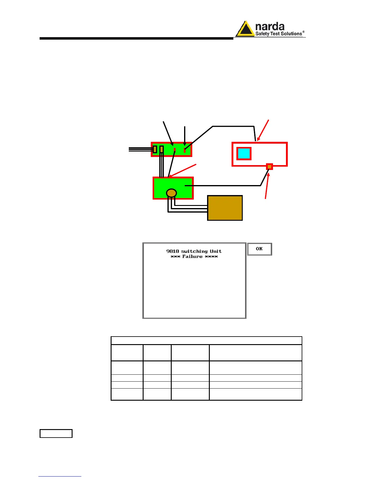
When, instead, the click rate N shall be determined counting the number of
“Switching” operations, a proper unit called “Switching Box” shall be
connected to the User Port of the PMM 9010.
In this case the EUT Power Connector will be used to feed the EUT through
the Switching Box and the hardware connection scheme will become then:
10.10 Diagnostic
In case the Switching Box unit is not connected – or anyway non properly
functioning – the following message is displayed:
Three Leds are visible on the Switching Operation Box, with the following
meaning:
TABLE 10-1 LED Status
ERROR
(Red)
DATA
(Yellow)
POWER ON
(Green)
Meaning
Blinking Off On
Condition at Power On, before
attempting any access to the Box
Off Off On Normal Condition after an access
Off Blinking On Normal Usage with data transfer
On Off On Error Condition (general)
In case of Error conditions, please check both HW connections and SW
settings at first, then call closest NARDA representative for help.
9010
User port
20dB Attenuator
220V
EUT
LISN
LISN remote
control
User port Output User port Input

 Loading...