11-18 PMM 9030/9060/9180 Frequency Extension
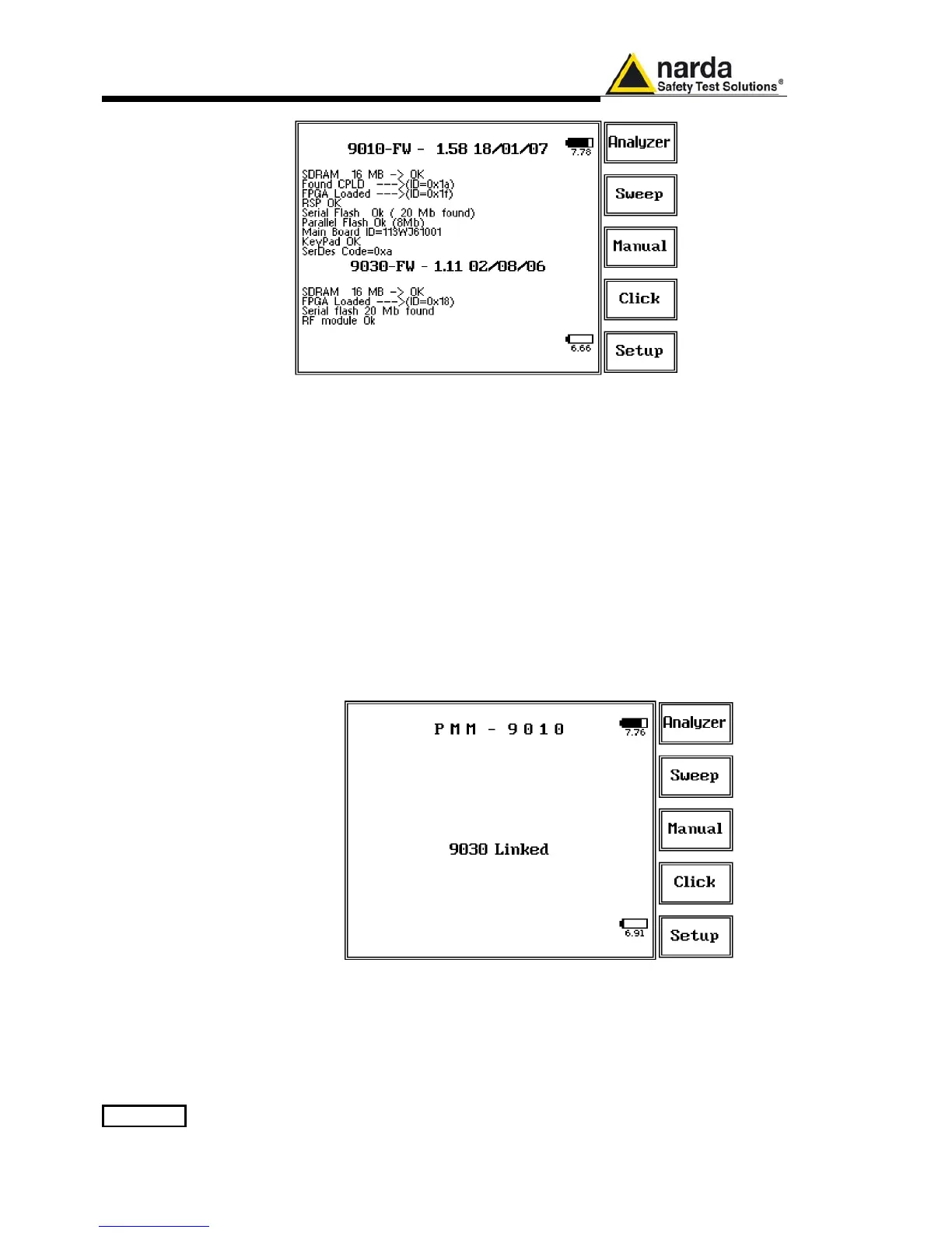
11.14.10 PMM 9010 +
PMM 9030/9060/9180
initial screen
The PMM 9030/9060/9180 is now ready to work in conjunction with the
PMM 9010.
11.14.11 LED on the
PMM 9010 and on the
PMM 9030/9060/9180
When the PMM 9030/9060/9180 is connected to PMM 9010, the yellow led
next to the RF input of PMM 9010 (“0dB led”) blinks to indicate that an
expansion unit is connected and that this BNC input shall be kept free of
any other connections.
The PW led on the back of the PMM 9030/9060/9180 remains on in fix
green color, to indicate the connection is good and stable.
When for any reason the link between PMM 9010 and PMM
9030/9060/9180 is interrupted, the PW led on the PMM 9030/9060/9180
blinks red (as just after the power ON), to indicate there is a connection
problem. After about 60 seconds in this condition, the PMM
9030/9060/9180 switches automatically OFF to save the battery.
11.14.12 PMM 9010 +
PMM 9030/9060/9180
main screen
After having selected any key and being returned to the main screen, the
usual appearance of the main screen is as follows:

 Loading...