A-D-4 LISN with PMM 9010
A-D.8 Marker Selecting this function a Marker is immediately enabled, and it appears on the
screen as a small black pointing down arrow corresponding to the highest
reading; simultaneously a small window shows up in the bottom left corner of
the screen, indicating the actual frequency and level read by the marker.
The Marker Off exits from the marker function.
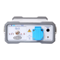
A-D.9 LISNs with
PMM Emission Suite
It is also possible, in a similar way, to run the performance test in the PC,
using the PMM Emission Suite.
Entering the sweep mode and clicking EXECUTE the PC software scans the
selected frequency band.
If a PMM LISN is to be checked it is also possible to automatically select the
lines and show on the same graph all the responses (not forgetting to
manually change BNC cable connection at LISN device’s Line before starting
the next sweep).
To do this please refer to the PEMS user’s manual and select proper
Ancillary.
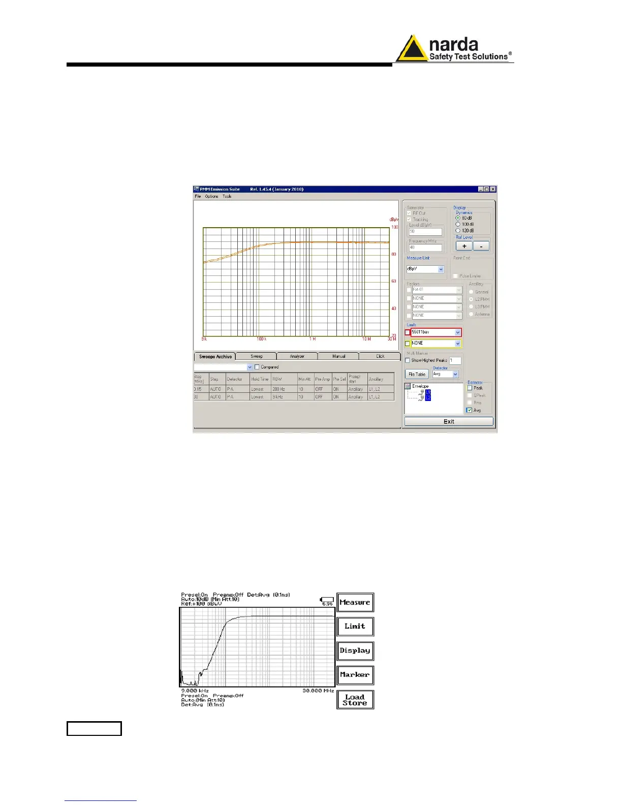
Frequency band
Some LISNs have a frequency band filter which can be introduced when
required.
PMM L2-16B for example is equipped with a switchable 150 kHz High Pass
filter.
The frequency response of such a kind of filter is also verifiable applying the
present procedure.
In this case the effects of the typical insertion loss of the circuit is summed to
the attenuation of the filter itself.
Example of the insertion
loss of a PMM L2-16B
LISN with the 150 kHz
High Pass filter activated.

 Loading...