General Information 9-13
9.15 PMM 9010/60P
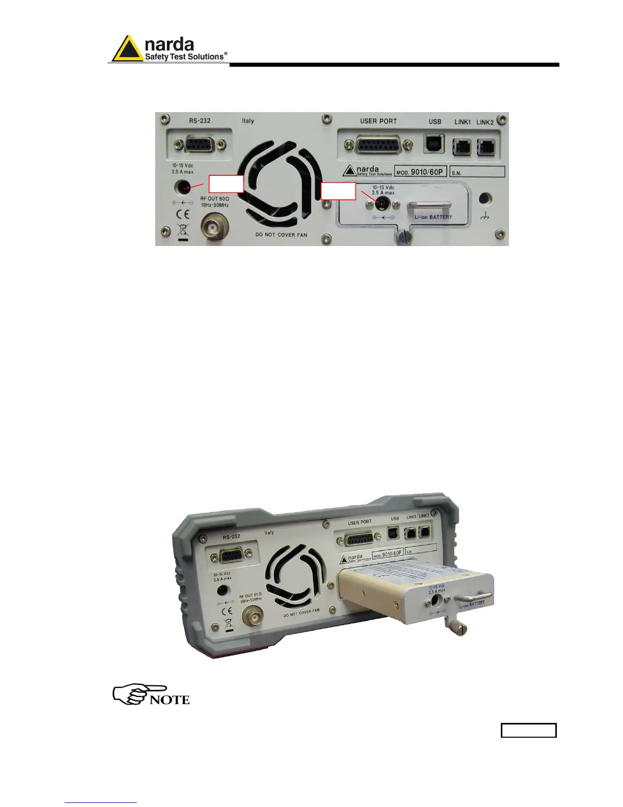
Rear Panel
Fig. 9-8 Rear Panel
Legend from left to right:
- RS232 9 pin, DB9 connector
- USER PORT User I/O Port
- USB Fully functional USB 2.0 Port
- LINK1/LINK2 Optical link connectors for PMM equipments (Link 2 for future implementation)
- Power Supply Power Supply Inputs for use to power the apparatus and simultaneously charge
its battery (PS1) and to simply charge the battery when it’s out of the receiver
(PS2).
- Output connector Tracking Generator Output
- Fan Cooling Fan controlled by firmware
- Replaceable Li-Ion Battery (Fig. 9-6) with main Battery Charger connector
- Earth ground connector
- Product Label and Serial Number
Fig. 9-9 BP-02 Replaceable Battery
To upgrade the firmware, install and use the PMM 9010/60P refer to
PMM 9010 section.
PS1
PS2