PMM 9030/9060/9180 Frequency Extension 11-5
11.6 PMM 9030 Front and Rear Panel
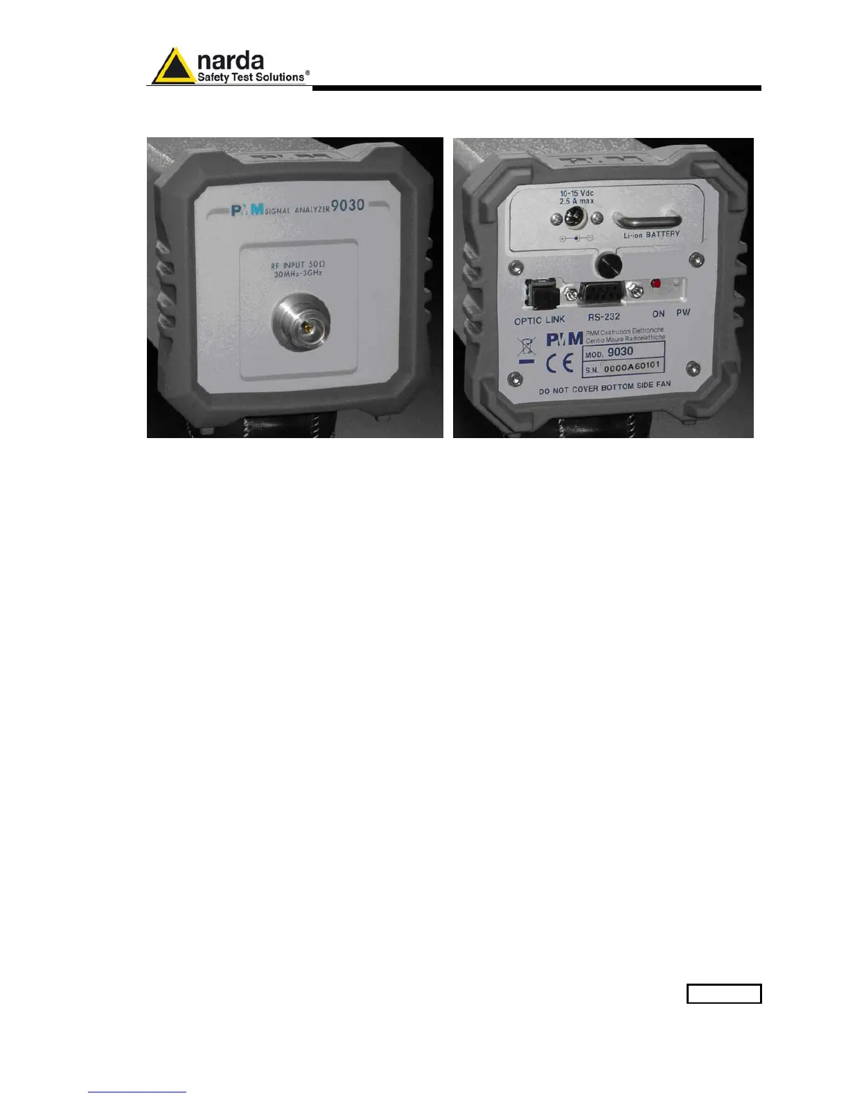
Fig. 11-1 9030 Front and Rear Panels
Only the input N connector is available on the front panel.
All other interfaces and connections are on the rear panel.
Legend top-down, from left to right on the rear panel:
- Replaceable Li-Ion Battery with Battery Charger connector
- OPTIC LINK Optical link connector for PMM 9010 or PMM 9010/03P/30P/60P
- RS232 9 pin, DB9 connector
- ON Power ON-OFF switch button
- PW Power ON/Communication led (Blinking Red at power-on until communication
with PMM 9010 or PMM 9010/03P/30P/60P is
established, then Fixed Green during
normal communication)
- Product Label and Serial Number

 Loading...