A-D-2 LISN with PMM 9010
A-D.5 Measure the
Insertion Loss
(Voltage Division
Factor)
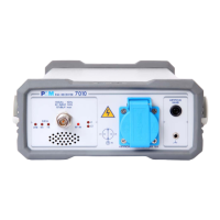
Be careful no voltage or mains network is connected to the device
(LISNs or others) under test.
It is possible to check the test setup by connecting the RF Output of the
PMM 9010 to its RF Input via one of the two BNC RF Coaxial cables
(eventually, in two steps, one of the cables at first and then the other).
In case the response is not as flat as expected please check the cables
and eventually run the Autocalibration of the receiver, then repeat the test.
Fig. A-D-1 Receiver verification
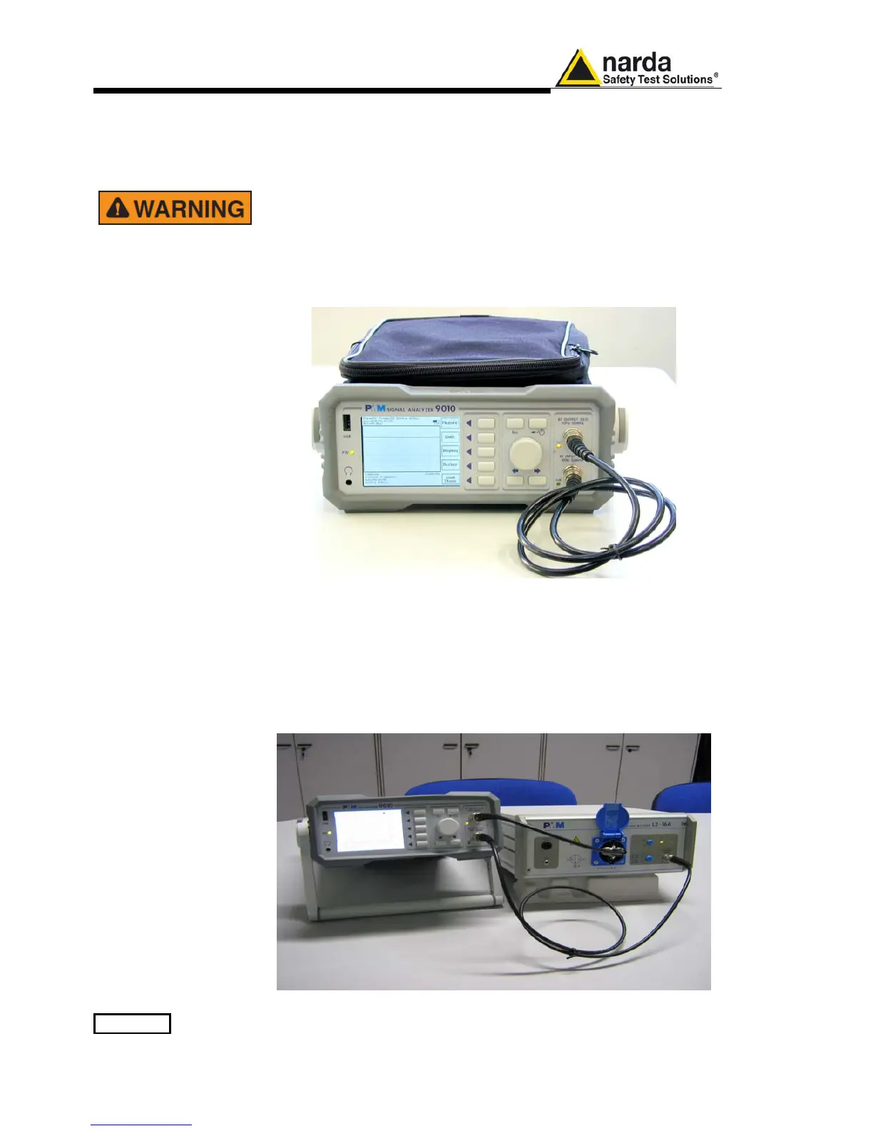
A-D.6 Connecting the
LISN under test
Before starting the measurement the LISN must be connected to the PMM
9010 EMI Receiver.
Connect one end of the first coaxial cable to the RF Output of the
PMM 9010 and the other end to the proper Mains Supply-BNC
Adapter.
Connect the second coaxial cable between the Receiver port
connector on the LISN and the RF Input connector of the PMM 9010.
Select the proper mains line under test (when possible).

 Loading...