General Information 1-5
1.8 Front Panel
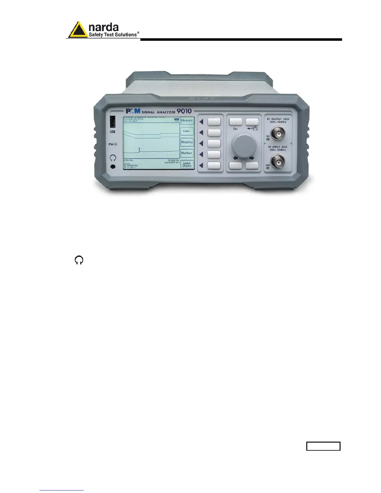
Fig. 1-1 Front Panel
Legend from left to right:
- USB USB 2.0 connection port (future implementation only)
- PW Power led
Indicates the power status
-
Earphone connector
To listen to the demodulated signals
- DISPLAY Main display
To graphically show the instrument status
- User keys 5 command keys
To select the various available functions
- Controls Rotary Knob, Left and Right (decrease / increase) Arrow Keys; Esc; Enter/Switch Key
The Rotary Knob and the Arrows Keys can be used to increase and decrease the
setting values; the Esc key allows to return to the previous status/display;
the Enter/switch key is used to confirm a set value and to switch On and Off
the equipment
- Input and Output connectors
Tracking Generator Output and Receiver Input
- RF Output led “ON”
Indicates when the internal generator is switched ON
- RF Input led “0dB”
Is ON when the input attenuator has been set to 0 dB; blinking when
PMM 9030/9060/9180 is connected through fiber optic cable and properly
communicating with 9010

 Loading...