1.4 Installing the Expansion KSU(s)
1.4.1 General
Each Expansion KSU is connected to the Main KSU individually. The EXIFB-C1 card must be installed
in the Main
KSU (1228M-B) .
1.4.2 Unpacking (EXIFB-C1)
Unpack the EXIFB-C1 and check it against physical damage.
Table 2-3 EXIFB-C1 Packing List
Items List of Contents QTY
EXIFB-C1 EXIFB-C1 PCB 1
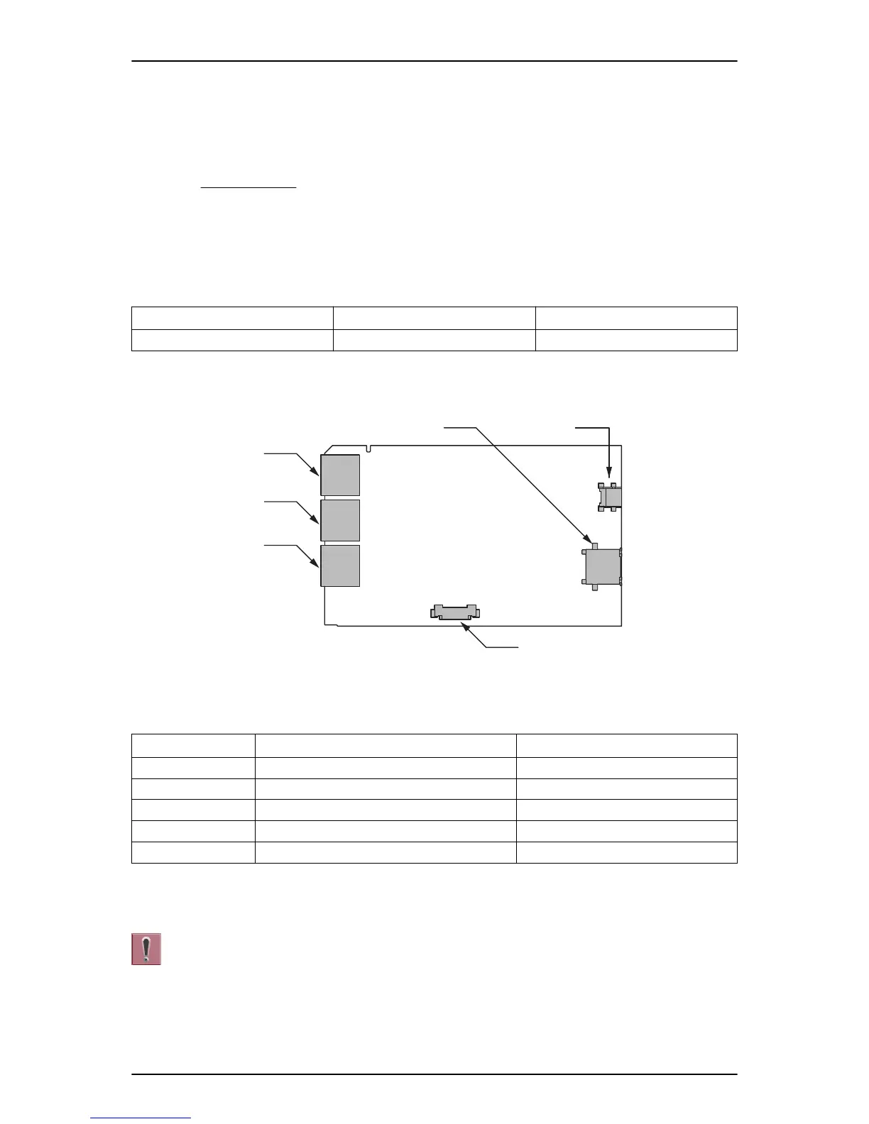
1.4.3 Connectors Location (EXIFB-C1)
Figure 2-11 Connectors of EXIFB-C1
Table 2-4 Connectors of EXIFB-C1
No. Connectors Connectable Devices
J1 Expansion Connector (Not used) -
J2 Expansion Connector Expansion KSU 2
J3 Expansion Connector Expansion KSU 1
J4 Mother PCB J1 connector on 084M-B1
J5, J6 Debug Purpose (Not used) -
1.4.4 Installing the EXIFB-C1 PCB
Do Not Power on until all installations have been completed.
1. Turn off the system power and disconnect the AC cord from KSU.
ISSUE 5.0
SL1100
Hardware Manual 2-9

 Loading...


