Issue 6.0 NEC SL1100
6 - 14 Network Design Considerations
Not all network hardware supports QoS and each manufacturer has their own
methods of implementing QoS. The explanations below are as generic as possible.
The installer/maintainer of the data network should be familiar with the QoS
characteristics of their equipment and should be able to configure the equipment
accordingly.
Quality of Service is commonly used to describe the actual implementation of
prioritization on network hardware. This prioritization (at Layer 2 and Layer 3 of the
OSI model) is described in Figure 6-1 Layer 2 Diagram (802.1Q) on page 6-5.
6.1 Prioritization
When data is transmitted through a network, bottlenecks can occur causing
the available bandwidth to be reduced or the data to increase. This impacts
the packet delivery.
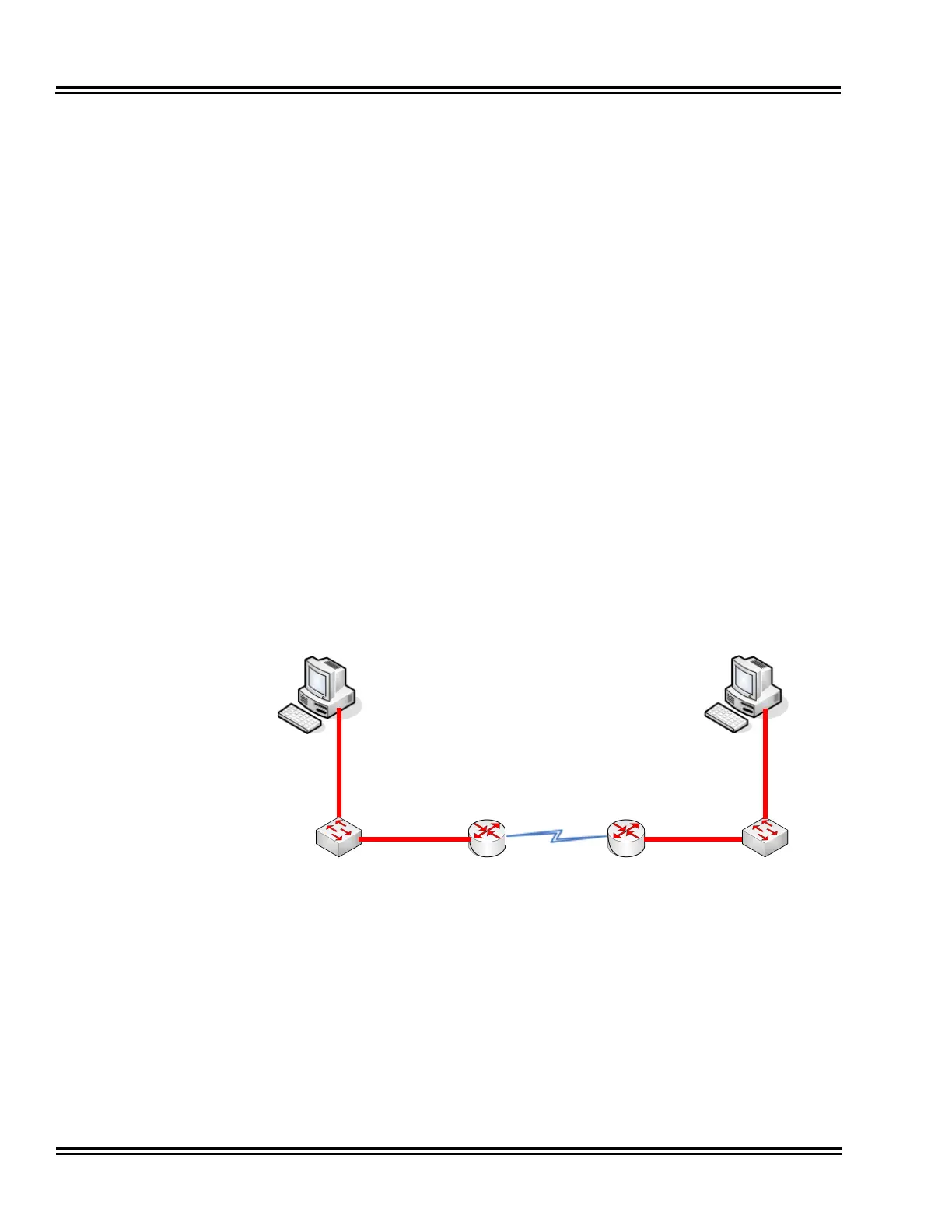
Consider data communication between the two computers shown in the
diagram Figure 6-1 Layer 2 Diagram (802.1Q). The Hosts can transmit data
at 100 Mbps. When a packet from Host A, destined for Host B, reaches the
router, the available bandwidth is reduced to 256Kbps and the packet flow
must be reduced. Figure 6-3 Network Bottleneck Example shows a diagram
of this condition.
For this example, each end of the network has only.one host Typically, many
hosts are sending data over the narrow bandwidth. The routers buffer packets
and transmit them over the WAN lines as efficiently as possible. When this
occurs, certain packets are dropped by the router and some packets are
delayed.
Figure 6-3 Network Bottleneck Example
256Kbps
Private Circuit
(Leased Line)
Data Switch
Router
Host A
Router
Data Switch
Host B
100Mbps100Mbps
100Mbps
100Mbps

 Loading...


