NEC SL1100 Issue 6.0
Networking Manual 4 - 5
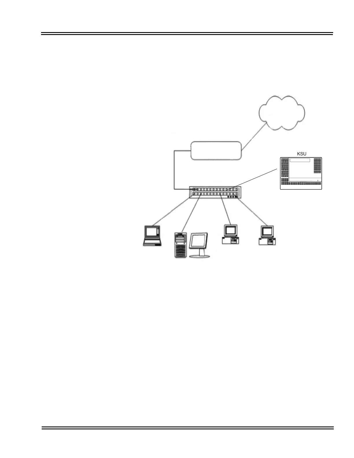
Now connect the CPU-B1/VoIPDB Ethernet Port to the switch port, using a
standard Cat-5 patch cable. The NEC SL1100 is now configured on the
network and should be accessible by other devices on the network. Refer to
Figure 4-2 Example Configuration 1 - Adding the NEC SL1100 KSU to the
Network.
Figure 4-2 Example Configuration 1 - Adding the NEC SL1100 KSU to the Network
Router
(Default Gateway)
WAN,
Internet, etc.
192.168.1.254
192.168.1.50
192.168.1.32
192.168.10.11 192.168.1.10
NEC SL1100 KSU
with CPU Installed
192.168.1.200
Switch

 Loading...


