4. Advanced Operation
PROGRAMMABLE AC POWER SOURCE
124
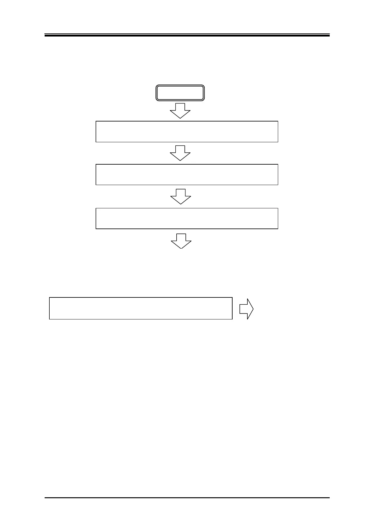
4.3.4 Process Flow in a Step
Figure 4–14 shows the process flow in one step. The End operation causes the transition as shown in
Figure 4–15.
ステップ開始位相設定がオンなら,設定された開始位相から
出力を開始します。
開始
ステップ終了位相設定がオンなら,設定された終了位相に達
するまで出力状態を保持します。
次ステップへ移行
指定されたステップ時間の間,設定に従い出力します。
Transitions to the next step
Start
If the Start Phase is set to ON, the output starts with the set start phase.
During the specified Step Time, output is performed according to the setting.
If stop phase setting is on, the output state is kept until the step reaches the
specified Stop Phase.
Figure 4-14 Process Flow through Simulation Steps
電源変動試験終了操作が行われたら,初期ステップへ移行し
ます。
初期ステップへ移行
=電源変動試験終了
When simulation stop operation is executed, the execution transitions to Initial
Step.
Transitions to the Initial Step
= End of simulation
Figure 4-15 Stop Operation
4.3.5 Editing Simulation
-------- Notes ------------------------------------------------------------------------------------------------------------
When the power is turned off, edited contents of the simulation are cleared, and all simulations
have the default setting values when it is started next time. To keep the edited contents of
simulation, save them in the Simulation Memory (see 4.3.8).
When a simulation is loaded from memory, the simulation you are editing is discarded.
You can also turn on output on the Simulation Edit View. In this case, the output will be set to
the state set in the initial step when Power Fluctuation Testing was last compiled (see 4.3.7).
-----------------------------------------------------------------------------------------------------------------------------