5. Description of Screen and Menu
PROGRAMMABLE AC POWER SOURCE
218
5.1 Screen Configuration
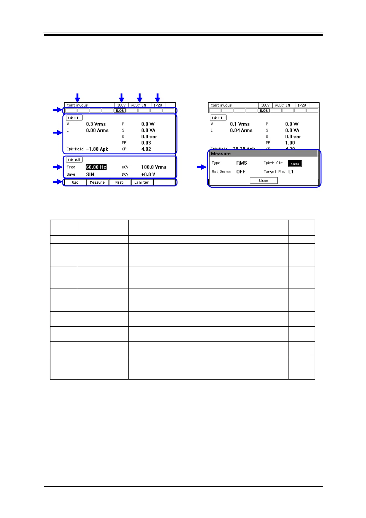
Figure 5–1 shows the basic screen configuration. It consists of display areas marked as "a" to "i".
The description of each area is shown in Table 5-1.
Figure 5-1 Component Name (Display Areas on the Screen)
Table 5-1 Component Name (Display Areas on the Screen)
Symbol Area name Description Refer
to
a Screen title Title of the currently displayed screen. —
b Output range Current output range.
3.4.2
c Output mode Current output mode. It is displayed in the format of
"AC/DC mode - Signal source."
3.4.1
d Output phase
configuration
Current output phase configuration in the system.
1P2W: Single-phase two-wire/1P3W: Single-phase
three-wire/3P4W: Three-phase four-wire
1.2
e Status icon The area where an icon is displayed when the product
enters the specific state, for example, when the limiter is
activated.
5.1.1
f Measured value
area
The measured values are displayed. In the Simple View,
three items are enlarged.
3.4.10,
3.4.11
g Output display
area
The output setting is displayed. Make the output settings
in this area.
3.4
h Soft-key
function
Shows the functions assigned to the soft-keys below.
3.3.3
i Window The window where the confirmation message is
displayed or you change the settings. It is displayed as
needed.
3.3.4
a b c d
e
f
g
h
i