4.6 Using Clipped Sine Wave
DP Series/DP Series Type R
147
2.
Turn on the power switch of the object to be measured.
3.
Turn on the output.
4.
Read current peak-hold value (Ipk-Hold). This is the maximum inrush current value.
4.5.4 Measurement Tips
You can see the difference among inrush currents at each power-on phase by changing the
phase setting at output on (see 3.4.7) before turning on the output.
The object inrush current cannot be measured correctly when the maximum peak current
exceeds the one that can be supplied by this product or the peak current limiter is activated.
Correct peak value measurement may not be accomplished for a very small load impedance,
such as when there is a short at the output terminal.
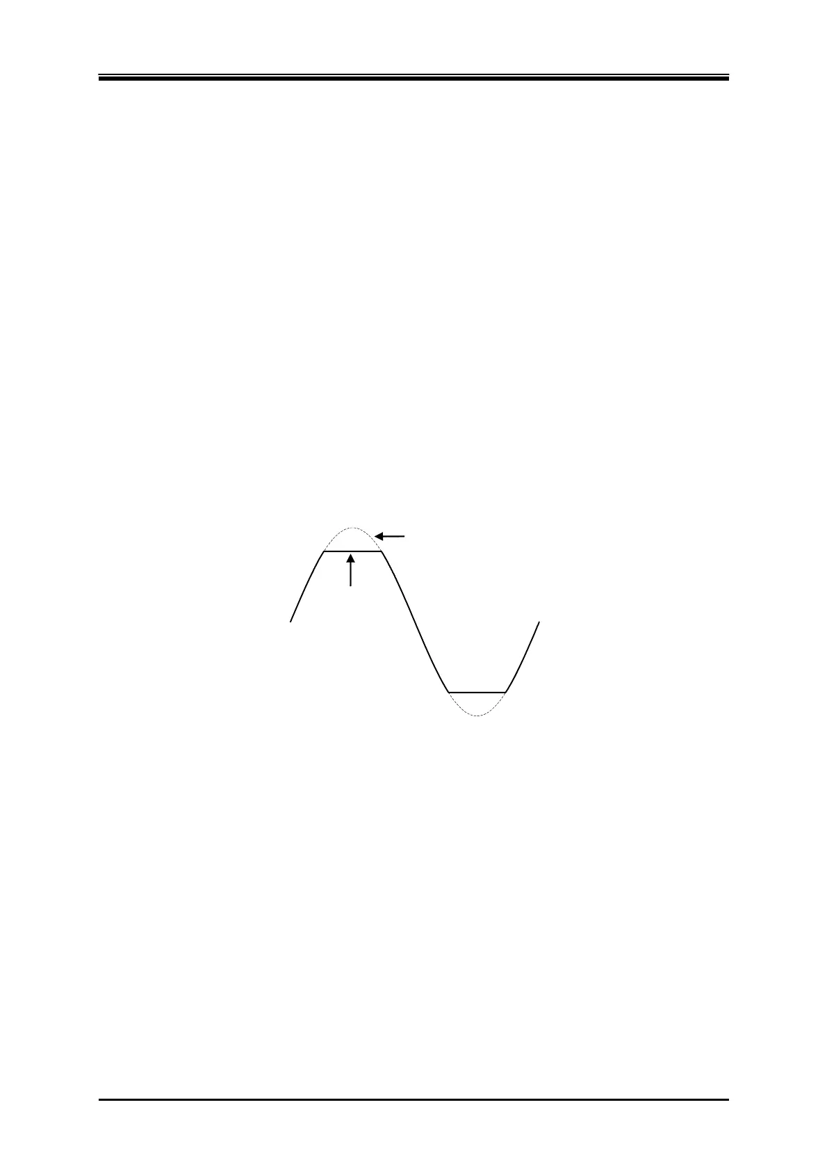
4.6 Using Clipped Sine Wave
Clipped sine wave is the waveform that has its sine wave peak clipped as shown in Figure 4–22. This
product can select the clipped sine wave as the output waveform.
もとの正弦波
クリップ
正弦波
Original sine
wave
Clipped
sine wave
Figure 4-22 Clipped Sine Wave
The depth of clip is set using the crest factor or clip ratio. Each of them is defined by the following
expression. The clip ratio is set in percentage.
Crest factor = Peak value/RMS value
Clip ratio = Clipped sine wave peak value/Original sine wave peak value
As shown in Table 4-8, the output voltage setting method differs depending on the clip depth setting
method. Therefore, a clip ratio less than 100% makes the output voltage smaller than the setting.