3.4 Using the Continuous Function
DP Series/DP Series Type R
55
3.4 Using the Continuous Function
3.4.1 Setting the AC/DC Mode and the Signal Source
The description of the AC/DC mode is shown in Table 3-7. The description of the signal source is
shown in Table 3-8. The selectable combinations of the AC/DC mode and the signal source are
shown in Table 3-9.
-------- Notes ------------------------------------------------------------------------------------------------------------
If the load is a transformer whose core saturates even with small amount of DC component,
select the AC mode.
If you output AC less than 40 Hz, select the ACDC mode. You cannot set the frequency to less
than 40 Hz in the AC mode.
In the AC mode, if the output is a waveform that has a long cycle or is dissymmetric in terms
of positive and negative (e.g. when the phase is changed rapidly or the different values are set
for the positive and negative in the peak current limiter), the waveform may be transformed by
the DC component removing function of the AC mode. If you want to make the output
waveform similar to the signal source, select the ACDC mode.
-----------------------------------------------------------------------------------------------------------------------------
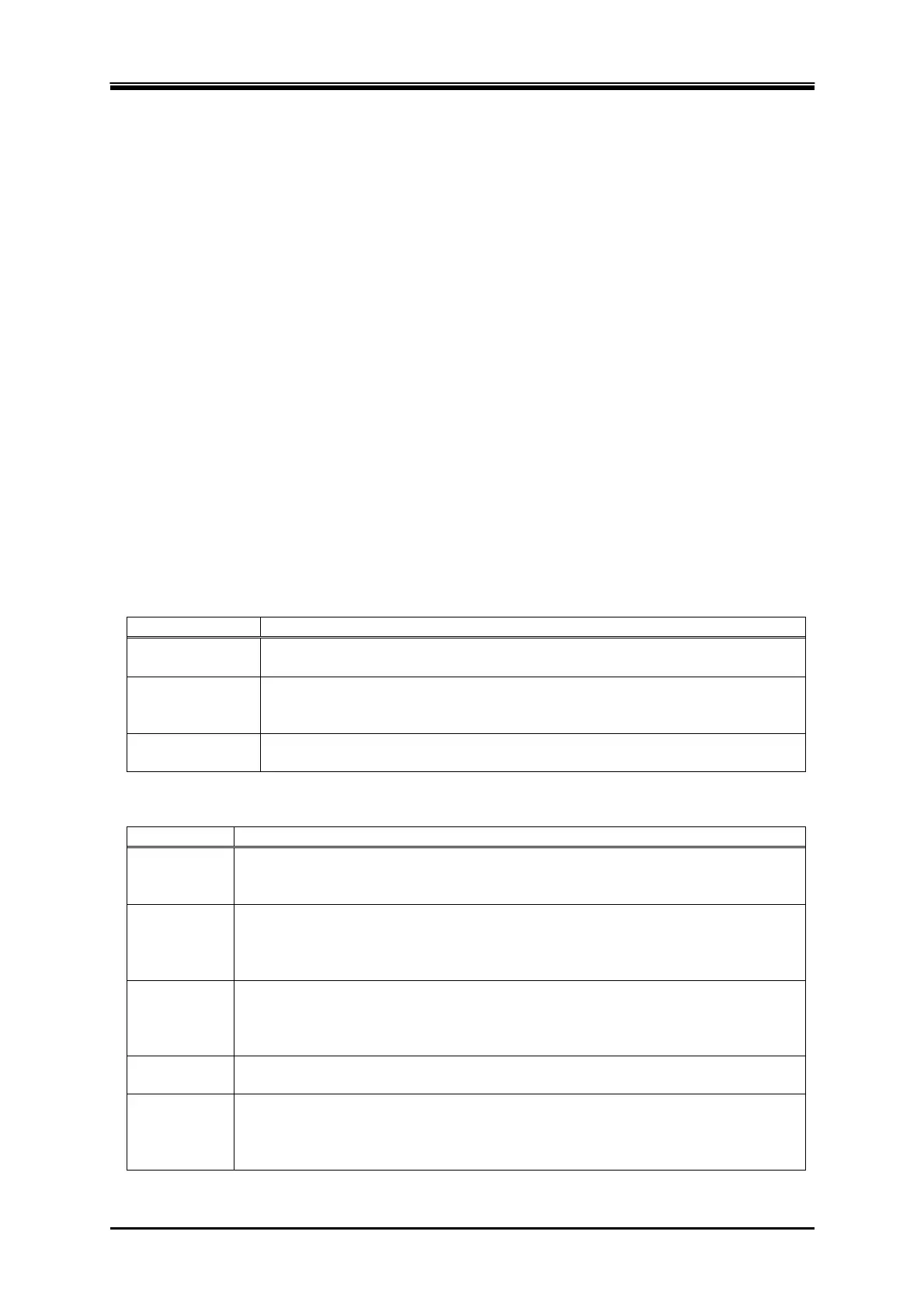
Table 3-7 Description of the AC/DC Mode
AC/DC mode Description
AC Only the AC voltage can be set. The AC coupling is used between the signal
source and the amplification section and the DC component is removed.
ACDC The AC voltage and the DC voltage can be set respectively. The DC coupling
is used between the signal source and the amplification section and both of
the AC component and the DC component are output.
DC Only the DC voltage can be set; the AC voltage is fixed to zero. The DC
coupling is used between the signal source and the amplification section.
Table 3-8 The Description of the Signal Source
Signal source Description
INT The signal source is internal. Set the output voltage, output waveform, frequency,
output on phase, and output off phase through the control panel or the remote
control.
VCA The signal source is internal. The output voltage can be controlled with the
external DC input signal. The output voltage setting cannot be set through the
control panel or the remote control. All conditions except for output voltage
setting is same as INT.
SYNC The signal source is internal. The frequency of the internal signal source is
synchronized with the external input signal or the power line. The frequency
setting cannot be set through the control panel or the remote control. All
conditions except for output frequency setting is same as INT.
EXT The signal source is external. Outputs the amplified external input signal. Set the
voltage gain through the control panel or the remote control.
ADD The signal source is the total of the external and the internal signal source. Set the
voltage gain for the external input signal, output voltage for the internal signal
source, output waveform, frequency, output on phase, and output off phase
through the control panel or the remote control.