3. Basic Operation
PROGRAMMABLE AC POWER SOURCE
44
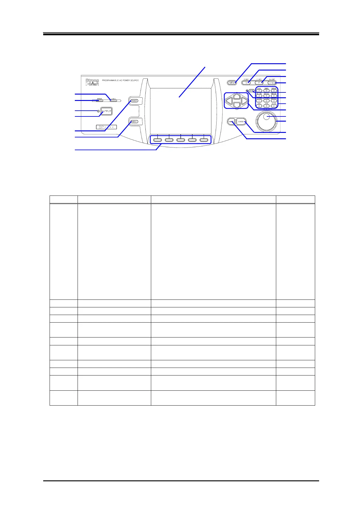
3.1.3 Control Panel
Figure 3-3 Component Name (Control Panel)
Table 3-3 Component Name (Control Panel)
Number Name Description Refer to
1 LIMIT LED Illuminates when the peak current limiter,
RMS current limiter, or wattage limiter
activates.
[DP series Type R only]
Flashes when the reverse power flow
satisfies one of the following conditions.
The reverse power exceeding 40% of the
electric power capacity has lasted for 3
minutes.
The reverse power exceeding 40% of the
electric power capacity has occupied 20%
in duty cycle.
4.1
2 ERROR LED Illuminates when an error is detected.
8.1
3 OUTPUT LED Illuminates in the output on state.
3.4.8
4 OUTPUT key Turns the output on or off.
3.4.8
5 RANGE key Switches between the 100 V and 200 V
ranges.
3.4.2
6 MENU key Displays the root menu.
3.3.1
7 Soft-key Assigned with the functions displayed at the
bottom of the LCD screen.
5.1
8 LCD screen Displays the measured values or menu.
5.1
9 MEMORY key Displays the Memory View.
4.8
10 V key Opens the numerical entry box for the
output voltage setting.
3.4.4,
3.4.5
11 F key Opens the numerical entry box for the
frequency setting.
3.4.6
1. LIMIT LED
2. ERROR LED
3. OUTPUT LED
4. OUTPUT key
5. RANGE key
6. MENU key
7. Soft-key
8. LCD screen
9. MEMORY key
10. V key
11. F key
12. I key
13. SHIFT key
14. SHIFT LED
15. Numeric keypad
16. Arrow key
17. Jog
18. Shuttle
19. ENTER key
20. CANCEL key