10.20 Clipped Sine Wave
DP Series/DP Series Type R
291
10.20 Clipped Sine Wave
The peak clipped sine wave can be output, based on the crest factor (CF) setting or the percent
setting to the peak value.
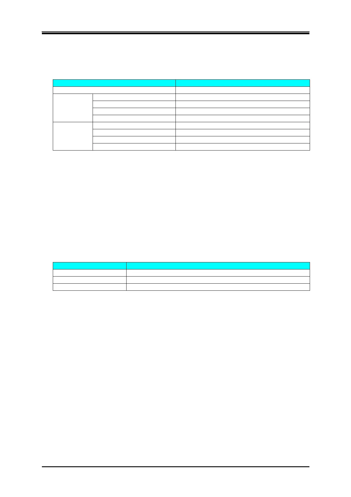
All models
Number of memories 3 (non-volatile)
CF
*66 *67
Variable range 1.10 to 1.41
Factory default 1.41
Setting resolution 0.01
Effective value correction Yes
Clip ratio
*66 *68
Variable range 40.0 % to 100.0 %
Factory default 100.0 %
Setting resolution 0.1 %
Effective value correction None
*66: In the polyphase model, polyphase system, and polyphase output of the Multi-phase model,
these are the settings for the phase voltage.
*67: The crest factor is represented as "voltage peak value/voltage effective value." It is 1.41 for sine
wave.
*68: When the clip ratio is specified, the peak is clipped by the voltage corresponding to the
specified % to the peak value of the setting voltage (100 %).
Example) For the output voltage setting of 100 Vrms and the clip rate of 80 %, the peak is
clipped at 113.1 Vpk.
10.21 Arbitrary Wave
This uses the waveform data saved in the internal memory, which is transferred and recalled using
the external interface or USB memory.
All models
Number of memories 16 (non-volatile)
Waveform length 4096 words
Amplitude resolution 16 bit