Description
2-11
Part 1079832_04
E 2015 Nordson Corporation
Module Spacing
U
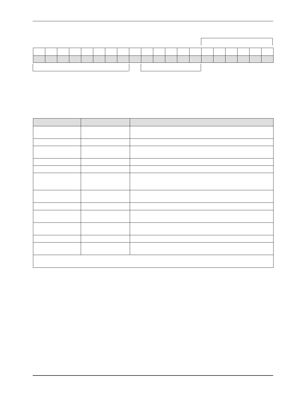
M S C X E 0 3 ‐ M X V I X / 0 2 5 . 0
1 2 3 4 5 6 7 8 9 10 11 12 13 14 15 16 17 18 19 20
Applicator Identification Options
Figure 2-8 Configuration code positions
Table 2-1 Explanation of Configuration Code Positions
Code Position(s) Description Values
1–4 Type of module
UMSC = Speed‐Coat (with boosted solenoid valve)
UMSN = Speed‐Coat (with non‐boosted solenoid valve)
5 Module options X = Standard
6
Type of module
spacing
E = Even spacing
X = 1 or 2 modules
7–8 Number of modules 01–10
9 Hyphen ‐
10 Style of cordset
T = T‐style (nickel RTD)
M = M‐style (platinum RTD)
C = C‐style (thermocouple)
11 Type of heated zones
X = Standard (1–22 modules, maximum of 4 zones)
8 = Low wattage zones (maximum of 8 zones)
12 Filter V = Standard vertical
13
Type of module
actuation
I= Independent
14
Type of solenoid
valve
X = None
15 Slash /
16–20
Module spacing
(inmm)
1–500 mm
NOTE: Available configurations are subject to change. Contact your Nordson representative for the most current
configuration choices. An S in the configuration code indicates a special option that is not included in this table.
 Loading...

