Description
2-10
Part 1079832_04
E 2015 Nordson Corporation
Explanation of the Applicator Configuration Code
Spray applicators are configurable, which means each applicator is
constructed according to the specific choices made when it was ordered.
You can determine the configuration of an applicator in either of the following
ways:
S Refer to the reference drawings and bill of materials in
Applicator‐Specific Reference Drawings in Section 8, Parts. These
drawings and the bill of materials are specific to your applicator.
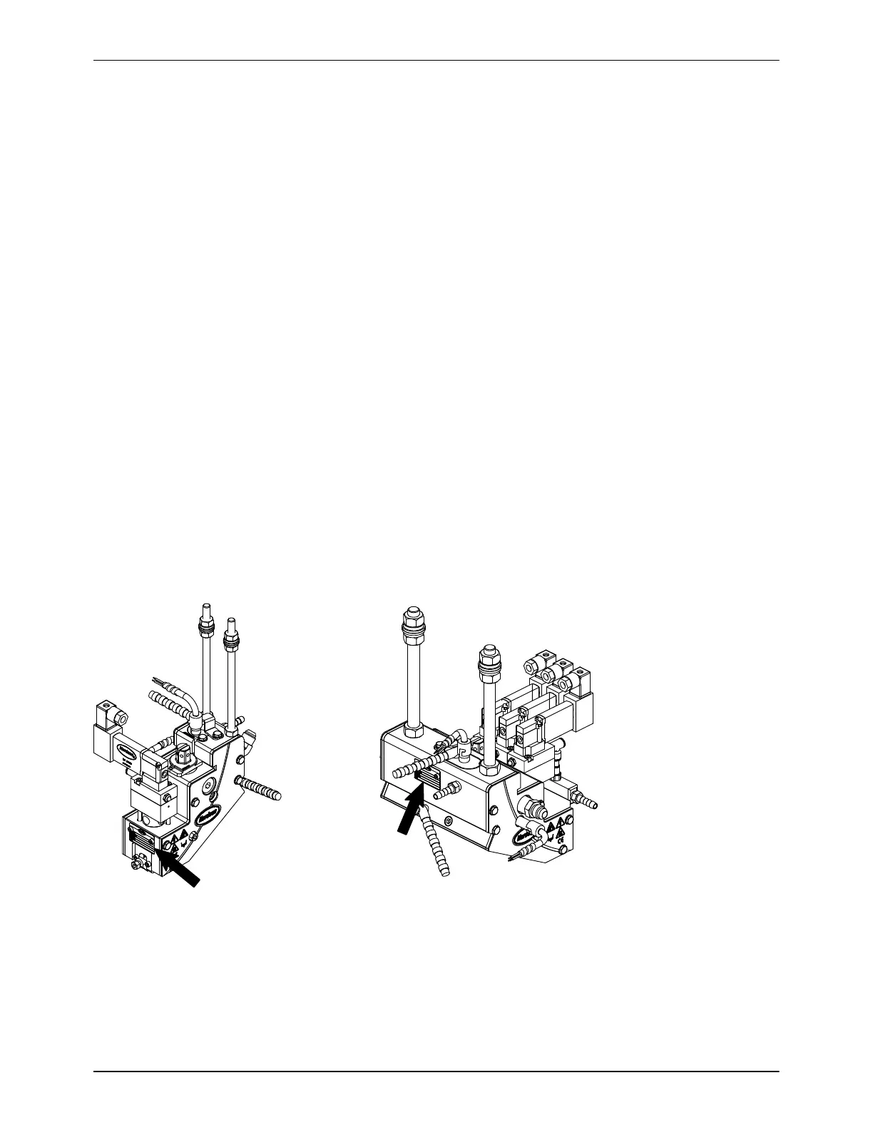
S Obtain the applicator configuration code from the MODEL portion of
the applicator identification plate. The identification plate is located on
the back or bottom of the applicator, as shown in Figure2‐7.
Compare the applicator configuration code to Figure2‐8 and
Table2‐1.
The example configuration code shown in Figure 2‐8 represents a spray
applicator that has
S three evenly spaced Speed‐Coat modules (UMSCXE03)
S an M‐style cordset(M)
S a standard number of heated zones (X)
S a standard vertical filter(V)
S independent air actuation (I)
S nosolenoid valves (because they are integral to the module) (X)
S 25‐mm module‐to‐module spacing (025.0)
Table 2‐1 provides an explanation of the configuration code values.
Figure 2-7 Location of the applicator identification plate on typical applicators
 Loading...

