Electrical System
11-28
Part 1079832_04
E 2015 Nordson Corporation
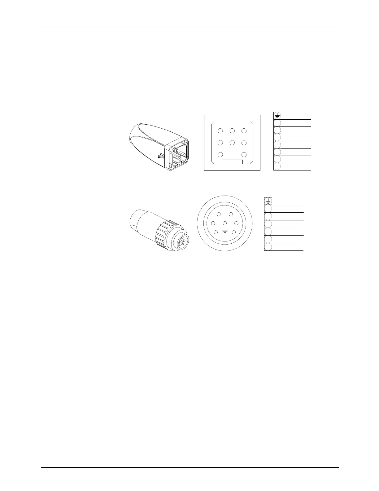
M‐Style Cordset Wiring Diagrams
These wiring diagrams are provided for your reference as needed during
troubleshooting activities. Refer also to Applicator‐Specific Reference
Drawings in Section 8, Parts, for wiring diagrams specific to your applicator.
M‐Style Cordset Pin Positions
GND
7
6
5
4
3
2
1
3
4
5
2
1
HEATER
HEATER
GROUND
SENSOR
6
SENSOR
7
Figure 11-24 M-style adhesive manifold cordset pin positions
3
4
5
2
1
HEATER
GROUND
SENSOR
6
SENSOR
6
5
4
3
2
1
HEATER
Figure 11-25 M-style heated air manifold cordset pin positions
 Loading...

