Chapter 8. Lithography
197
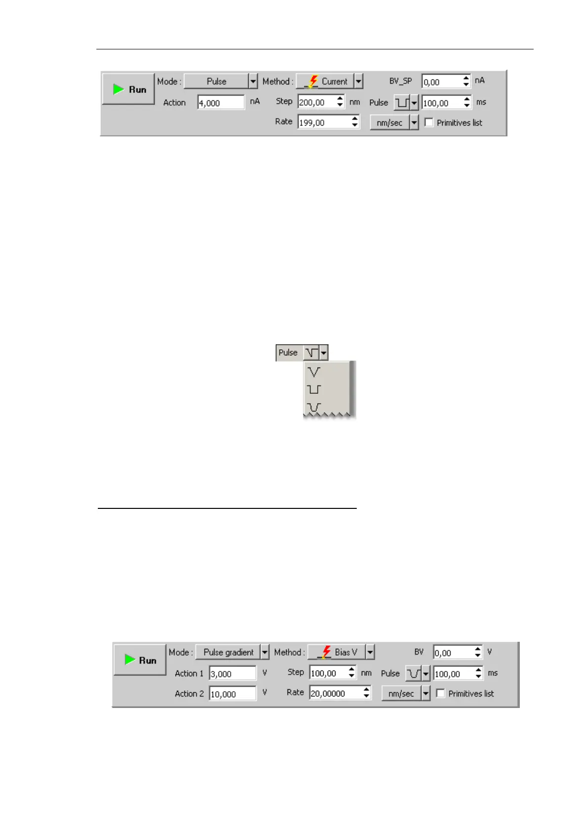
Fig. 8-51. Control panel for Current lithography
3. In the SetPoint field, define the exposure to be applied to the sample when the probe
moves to starting points of the template objects after finishing drawing or at the start of
lithography. For current lithography, the BV field is used; for current lithography, the
BV_SP field is used. Usually, this level is defined to be 0.
4. In the Rate field, define the lithography rate (the speed of moving the probe relative to
the sample surface).
The lithography rate influences on results of the sample exposure to lithography. The
lower is the rate, the deeper is the exposure and the better is the correspondence
between the template and the resulting surface.
5. In the Step field, define the time step between the pulses.
6. In the drop-down list to the right from the Step field, select the desired pulse shape.
Fig. 8-52. Pulse shape
7. In the Pulse field, define duration of a pusle.
Adjusting Pulse-Gradient Lithography Parameters
1. Decrease the level
SetPoint window by a factor of 2÷10 relatively to the SetPoint level
used for scanning.
2. In the Lithography Control panel, define the range of varying the exposure to be force
applied to the sample. Define the lower boundary of the range in the
Action 1 field and
the higher boundary in the Action 2 field.
Sign of the applied voltage influences significantly results of lithography. For example,
at large negative (<–8 V) voltage applied to the probe tip (Action parameter),
lithography can result not only in surface charging but also in local oxidation.
Fig. 8-53. Control panel for Charge lithography