Solver NEXT SPM. Instruction Manual
204
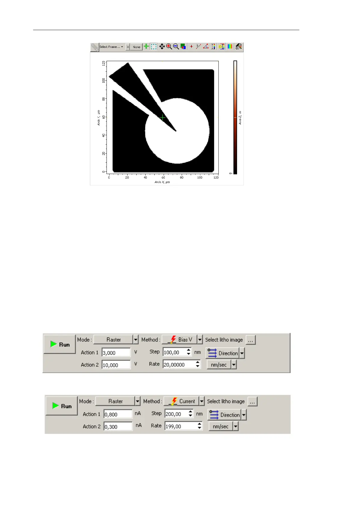
Fig. 8-64. Template for raster lithography is loaded
8.3.2.4. Adjusting Lithography Parameters
1. Decrease the level SetPoint window by a factor of 2÷10 relatively to the SetPoint level
used for scanning.
2. In the Lithography Control panel, define the range of varying the force applied to the
sample. Define the lower boundary of the range in the Action 1 field and the higher
boundary in the Action 2 field.
Value of Action 1 corresponds to the bottom of the color scale (black), while value of
Action 2 is linked to the top of the color scale (white).
Sign of the applied voltage influences significantly results of lithography. For example,
at large negative (<–8 V) voltage applied to the probe tip (
Action parameter),
lithography can result not only in surface charging but also in local oxidation.
Fig. 8-65. Control panel for Charge lithography
Fig. 8-66. Control panel for Current lithography