Chapter 8. Lithography
205
3. In the Rate field, define the lithography rate (the speed of moving the probe relative to
the sample surface).
The lithography rate influences on results of the sample exposure to lithography. The
lower is the rate, the deeper is the exposure and the better is the correspondence
between the template and the resulting surface.
4. In the Step field, define the time step between the pulses.
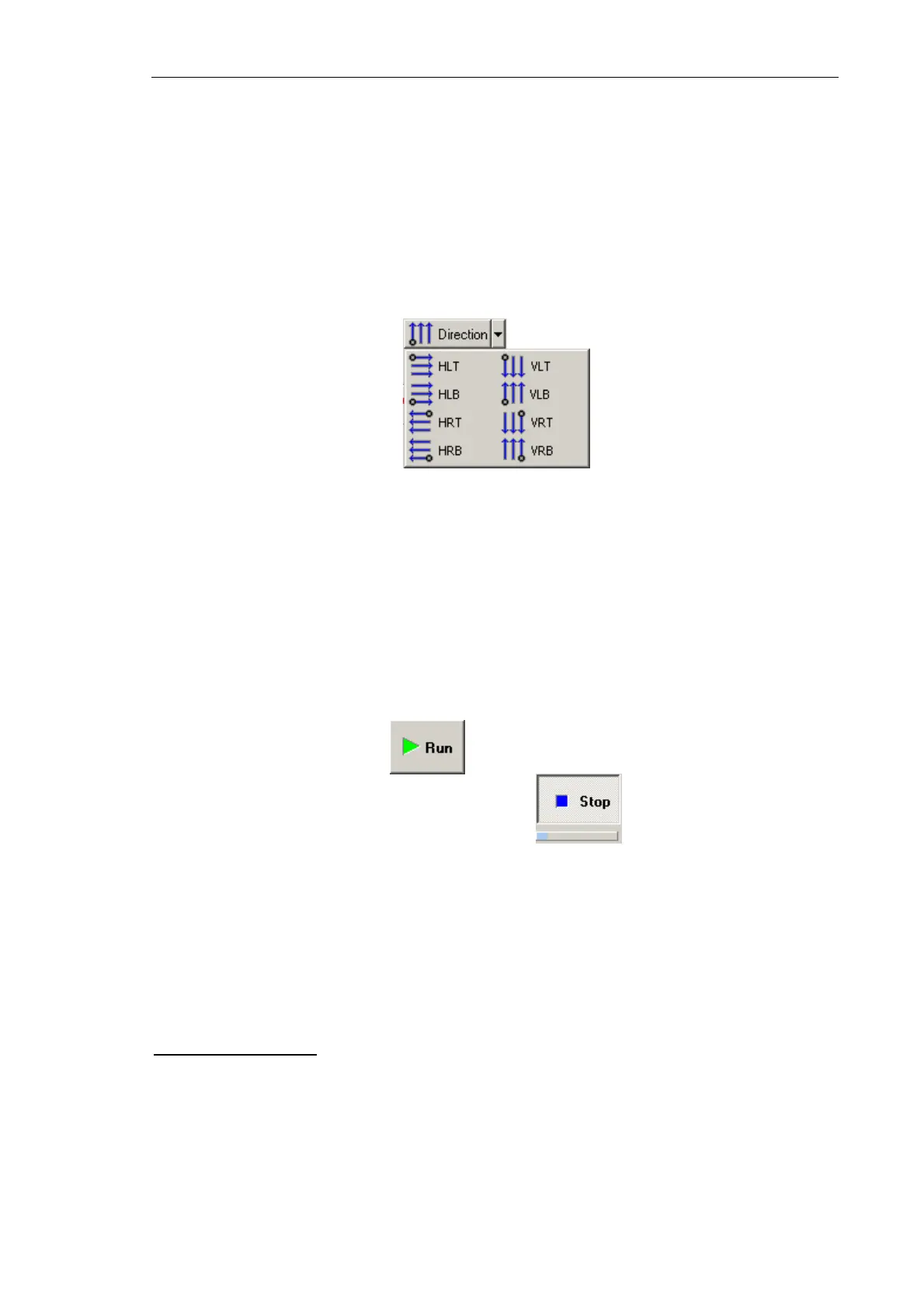
5. In the drop-down list, select the direction for lithography and position of the starting
point.
Fig. 8-67. Direction for lithography
8.3.2.5. Performing Lithography
When the lithography template is prepared (see i. 8.2.3.2 on p. 185) and the lithography
parameters are adjusted (see i. 8.2.3.3 on p. 186), the operator can start the lithography
process.
Operations of the electrical vector lithography procedures are the same for all modes.
To start lithography, click the button in the Control panel of the Litho window.
This will change appearance of the Run button to . Below the Stop button, the
progress bar will appear to display percentage of the procedure progress in blue.
When the procedure completes, the Stop button returns to its initial appearance.
The lithography process can be stopped by clicking the Stop button or by pressing the
<Esc> key. This will stop the process immediately. Next clicking the Run button would
start the lithography procedure from the very beginning, i.e. from the first template point.
Lithography Results
Take a scan of the sample by Kelvin Probe Microscopy. Results of electrical lithography
can be assessed with the surface potential distribution.
Results of charge lithography
Fig. 8-68 shows results of the raster lithography applied to the GaAs sample with
Action 1 = 10 V, Action 2 = –10 V by the NSG01/W
2
C probe.