Chapter 6. Preparing for Measurements
45
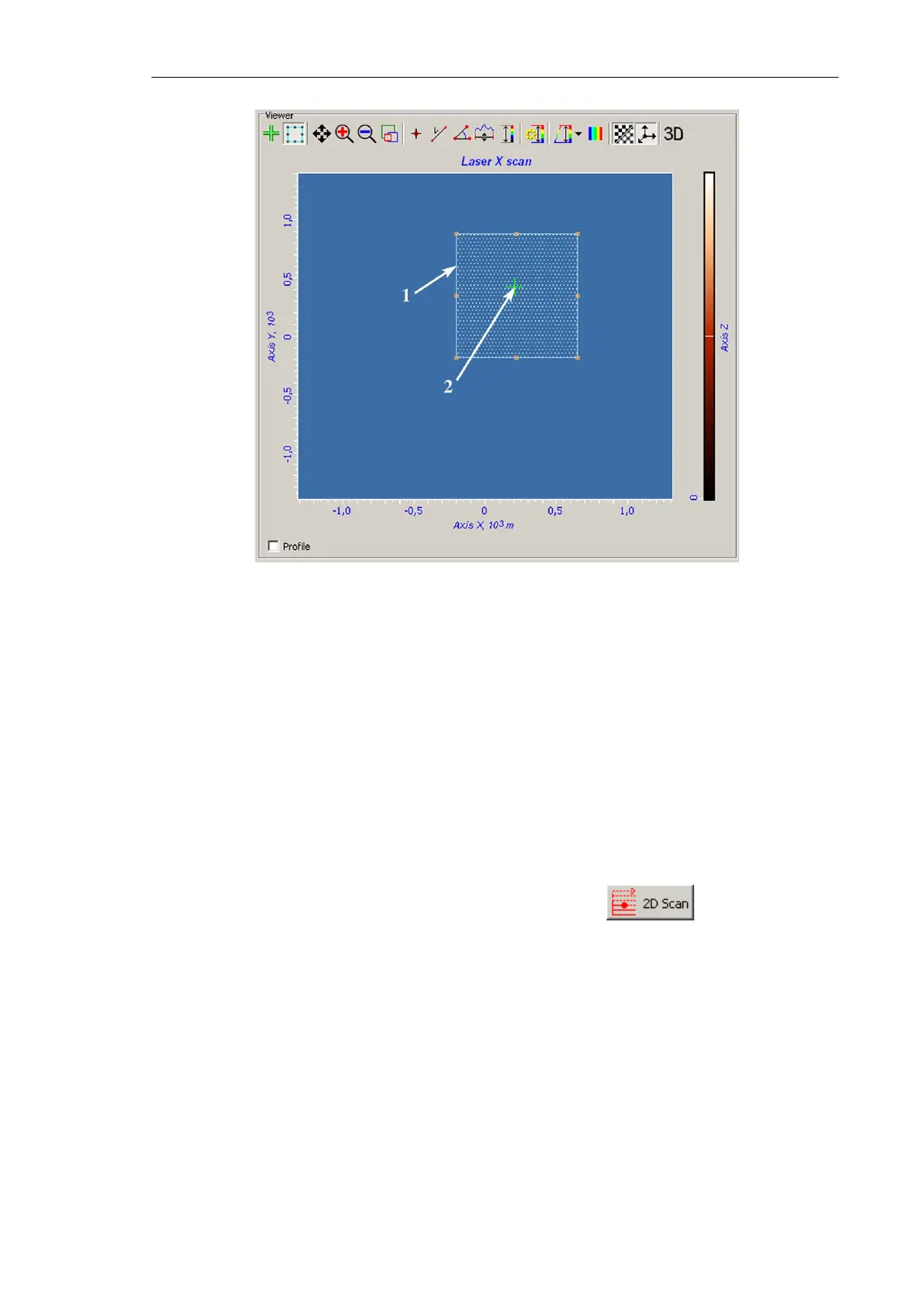
Fig. 6-35.
Viewer panel
1 – boundary of the selected search region;
2 – cursor pointing to the laser beam position
b. Move and/or resize the search area with the mouse (see. 1 on Fig. 6-35).
4. In the Scan Settings panel, define parameters of the search grid. Points of this grid
prescribe positions at which the laser signal will be taken. Define number of points in
the scan line in the Points in line input field and number of the lines in the Lines in scan
input field. To reduce the acquisition time, these numbers are recommended to be not
greater 20.
5. In the Signal drop-down list of the Scan Settings panel, select the Laser signal for
adjusting the system.
6. Start the procedure on searching the laser spot with the button. This starts
measuring the laser signal line by line over the grid and displaying the image acquired
by the photodiode in the 2D Viewer.
The measuring completes resulting in one of two following situations:
● The laser spot is caught and displayed in the Viewer (see Fig. 6-36). In this case, go
to step 7 for improved positioning of the laser spot;
● The Viewer misses the laser spot. This means that the cantilever is outside of the
search region or photodiode fails to catch the spot. You have either to enlarge the
search region and then to repeat steps 2-4 or to reposition the photodiode.