139
Other HFU Functions Section 5-2
Note (1) BUS1 and BUS2 are connected to SUB1 and SUB2 on the EDU.
(2) HFU event inputs and auxiliary outputs can be linked.
(3) Information output to buses can be accessed by the outputting Unit.
Bus Output
Assignment Settings
The parameters that can be set for bus output assignments are outlined
below. Refer to the following examples when setting parameters.
Note Make correct bus settings for each Unit, making sure the settings match oper-
ations in the EJ1 system.
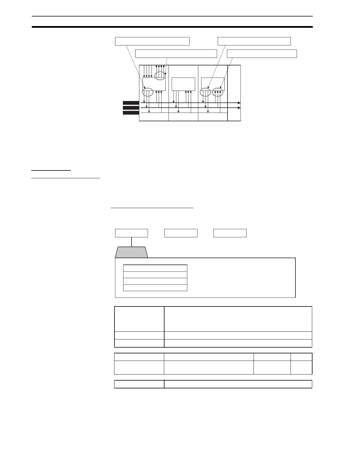
■ HFU Bus Output Assignments
• The status of functions shown in the following diagram can be allocated to
output them to bus outputs 1 to 3.
Note This parameter can be set only when operation is stopped.
When this parameter has been changed, the new setting becomes effective
the next time a software reset is performed for the Unit or the next time power
is turned ON.
Refer to Parameter List on page 193 for details on the settings.
CPUCPUCPU
BUS1
BUS2
BUS3
SUB1
SUB2
EV SUB
HFU TC2 TC4 EDU
Set using bus input assignments.
Set using bus output assignments.
Set using auxiliary output assignments.
Set using bus output assignments.
Temperature
Controller error
The Temperature Controller Error output will turn ON when any
bit between bit 0 and bit 13 is ON in the Device A Status. It can
be used to output EJ1 error status. Refer to Status Lists on
page 209 for details on Device A Status.
Event inputs 1 to 4 Outputs the ON/OFF status of event input 1 to event input 4.
Bus inputs 1 to 3 Outputs the status of bus input 1 to bus input 3.
Variable type Parameter name Setting range Default
F2/B2 Bus Output 1 to Bus Output 3 Assign-
ment (Common)
0 to 22 0
Conditions for use No special conditions
Bus output 2 and bus output 3 can be set in the same way.
Settable
parameters
Bus output 1
Temperature Controller Error
Event inputs 1 to 4
Bus inputs 1 to 3
Disabled
Bus output 2 Bus output 3