15
F3SJ-A
User’s Manual
Chapter1 Ratings
Overview and Specifications
E
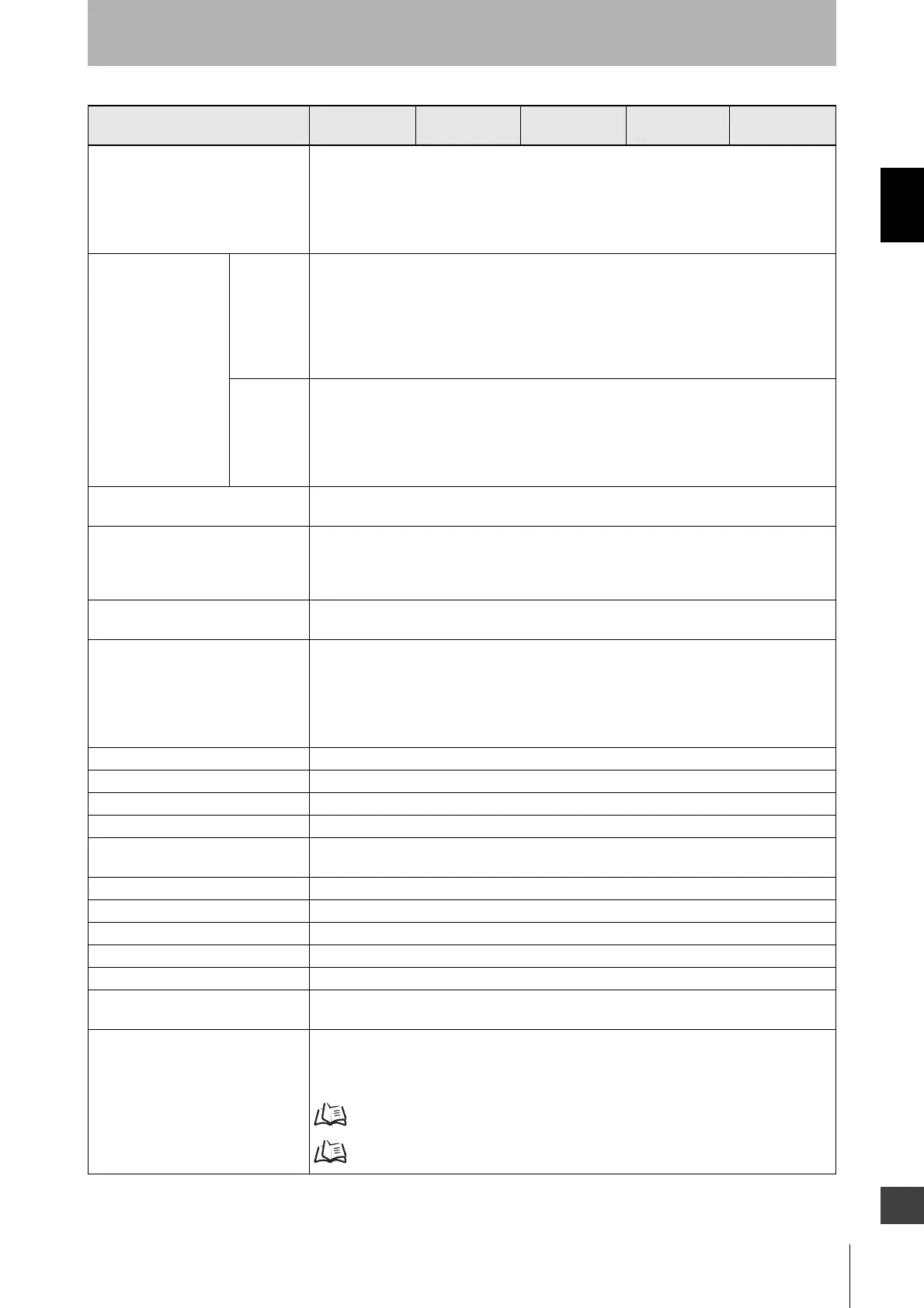
Input voltage Test input, interlock selection input, reset input, and muting input are all:
ON voltage: 0 to 1.5V (short-circuit current 3mA max.)
OFF voltage: 9 to 24Vs, or open
External device monitoring input is:
ON voltage: 0 to 1.5V (short-circuit current 5mA max.)
OFF voltage: 9 to 24Vs, or open
Indicators Emitter Incident light level indicators (green LED x 2, orange LED x 3): ON based on the amount of
incident light
Error mode indicators (red LED x 3): Blink to indicate error details
Power indicator (green LED x 1): ON while power is ON
Interlock indicator (yellow LED x 1): ON when in interlock/Blinks when in lockout
External device monitoring indicator (muting input 1 indicator), Blanking/ Test indicator (muting
input 2 indicator) (green LED x2): ON/Blink according to function
Receiver Incident light level indicators (green LED x 2, orange LED x 3): ON based on the amount of
incident light
Error mode indicators (red LED x 3): Blink to indicate error details
OFF-statet indicator (red LED x 1): ON when safety outputs are OFF/ Blinks when in lockout
ON-state indicator (green LED x 1): ON when safety outputs are ON
Muting error indicator, Blanking/Test indicator (green LED x 2): ON/Blink according to function
Mutual interference prevention
function
Interference light avoidance algorithm, operating range change function
Series connection Time division emission by series connection
- Number of connections: Up to 4 sets
- Total number of beams: Up to 400
- Maximum cable length between 2 sets of sensors: 15m
Test function - Self-test (After power ON, and during operation)
- External test (light emission stop function by test input)
Safety-related functions - Start interlock, restart interlock (The setting tool is required when muting function is used)
- External device monitoring
- Muting (Includes lamp breakage detection and override functions. F39-CN6 key cap for
muting is required)
- Fixed blanking (configuration by the setting tool is required)
- Floating blanking (configuration by the setting tool is required)
Connection method Connector method (M12, 8-pin)
Protection circuit Output short-circuit protection, and power supply reverse polarity protection
Ambient temperature During operation: -10 to 55°C (without freezing), During storage: -30 to 70°C
Ambient humidity During operation: 35 to 85%RH (no condensation), During storage: 35 to 95%RH
Ambient light intensity Incandescent lamp: receiving-surface light intensity of 3,000 Ix max., Sunlight: receiving-
surface light intensity of 10,000 Ix max.
Insulation resistance 20MΩ or higher (500VDC)
Dielectric strength voltage 1, 000VAC, 50/60Hz, 1min
Degree of protection IP65 (IEC60529)
Vibration resistance Malfunction: 10 to 55Hz, Multiple amplitude of 0.7mm, 20 sweeps each in X, Y, and Z directions
Shock resistance Malfunction: 100m/s
2
, 1,000 times each in X, Y, and Z directions
Connection cable, Series connection
cable (F39-JJRL, JJR3W)
Dia. 6 mm, 8-wire (0.15mm
2
x 8) with braided shield, Allowable bending radius R5mm
Extension cable (F39-JCA, JCB,
JDA, JDB)
Dia. 6.6 mm, 8-wire (0.3mm
2
x 4P, conductor resistance 0.058 ohm/m), with braided shield,
Allowable bending radius of R36mm.
(To extend a cable, use an equivalent or higher-performance cable (twisted-pair wire) , and do
not use the cable in the same duct as that for high-voltage cables or power cables)
For details about extension lengths (power cable length) p.22
For details about twisted pair wire (single connector cable)
p.159
F3SJ-A
N14
F3SJ-A
N20
F3SJ-A
N25
F3SJ-A
N30
F3SJ-A
N55

 Loading...


