76
Chapter3 Setting Adjusted to Application
F3SJ-A
User’s Manual
What can be done by the setting tool
Setting Change
In the setting console, all beams are set as a floating blanking zone.
With the PC tool for F3SJ, it is possible to set a range of floating blanking zone.
Configure for each CH in case of a series connection.
*1
If this function is enabled, and if either beam of F3SJ's ends is configured as a floating blanking
zone, it is excluded from floating blanking zone.
In figure 11, for example, bottom and top beams setting of blanking zone is ignored and a zone from
the 2nd to 15th beams is set as a floating blanking zone.
*2
Monitoring is disabled for non-sequential beam mode.
*3
To connect the setting console and F3SJ for which followings are configured, you must execute the
setting recovery on connection to recover factory shipment setting.
- Blanking zone is partially set
- Floating blanking monitoring function is being disabled
*4
In case of PC tool for F3SJ, other zone must be specified than outermost beams.
• Detection Capability
Detection capability of F3SJ can differ based on number of floating beams as shown below.
Minimum detection capability and number of beams for which safety output should be turned OFF
Limitation for Combination with Other Functions
You can use muting, fixed blanking, and warning zone functions in combination only with the PC tool
for F3SJ. Note that there is a limitation for setting with zones.
The setting console cannot combine these functions.
For details, see Setting Zone Adjacent Conditions p.91 .
Setting Zone Adjacent Conditions p.91
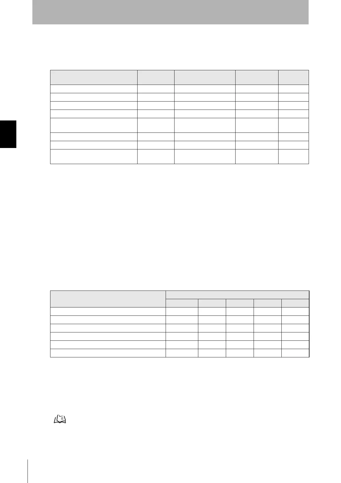
Function Initial Setting Available Setup Item Setting Console
PC Tool For
F3SJ
Floating Blanking Function Disable Enable/disable *3
Blanking Zone Bottom Beam 0 1 to Number of Beams – (Fixed to bottom)
Blanking Zone Top Beam 0 1 to Number of Beams – (Fixed to top)
Both End Beam Disabling Mode *
1
Disable Enable/disable *4
Floating Blanking Mode Sequential
Beam Mode
Sequential Beam Mode/
Non-Sequential Beam Mode
Number of Floating Beams 1 1~4
Number of Allowable Beams 0 0~3
Floating Blanking Monitoring Function *
2
Lockout Lockout / Monitoring
Disabled
–
Model
Number of Floating Beams and Detection Capability
Not specified Setting 1 Setting 2 Setting 3 Setting 4
F3SJ-AN14 series 14 mm 23 mm 32 mm 41 mm 50 mm
F3SJ-AN20 series 20 mm 35 mm 50 mm 65 mm 80 mm
F3SJ-AN25 series 25 mm 45 mm 65 mm 85 mm 105 mm
F3SJ-AN30 series 30 mm 55 mm 80 mm 105 mm 130 mm
F3SJ-AN55 series 55 mm 105 mm 155 mm 205 mm 255 mm
Number of beams for which safety output is turned OFF 1 beam 2 beams 3 beams 4 beams 5 beams

 Loading...


