Multi-function Compact Inverter 3G3MX2-EV2 User’s Manual (I666-E1)
Precautions for Correct Use
•
Setting the Motor Electronic Thermal Selection (b910) to 01 to 03 separates the inverter from
the motor electronic thermal function. This enables you to change the operation characteris-
tics of the motor electronic thermal function according to the thermal time constant of the
motor in use. For how to change these characteristics, refer to 7-8-2 Motor Electronic Ther-
mal Function on page 7-74.
•
To comply with UL standards, set the Electronic Thermal Load Rate Memory Selection at
Power-off (b914) to 01 (Enabled).
•
To set the electronic thermal function to work as with the conventional 3G3MX2 Series, set
the Motor Electronic Thermal Selection (b910) to 00 (Disabled).
•
To connect several motors to a single inverter, set the Electronic Thermal Level to the rated
output current of the inverter and install a thermal relay etc. for each motor.
•
Before setting the electronic thermal function, set the 1st/2nd Motor Capacity (H003/H203)
and the 1st/2nd Motor Pole Number (H004/H204) correctly according to your motor.
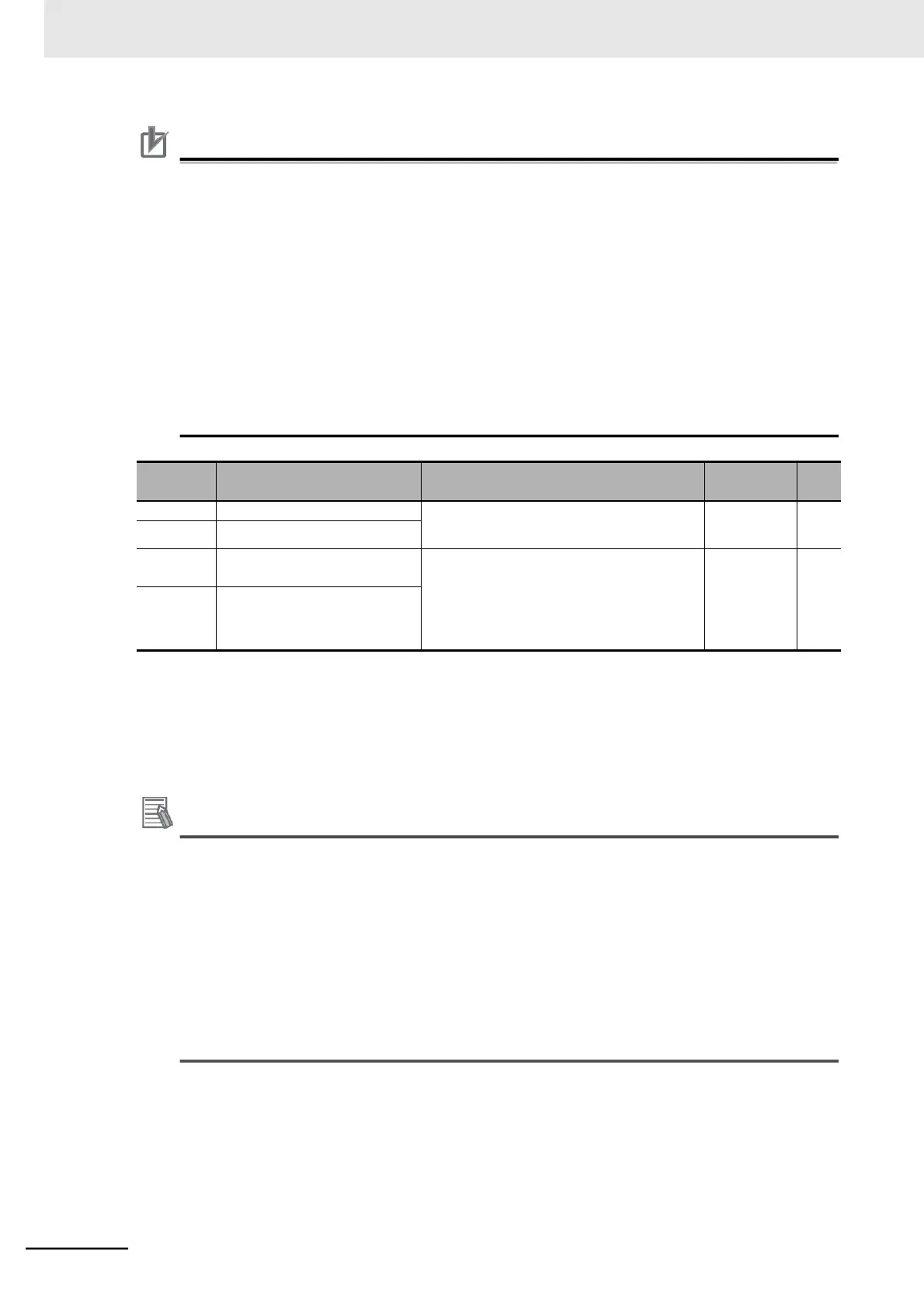
1st Electronic Thermal Level
0.20 Rated current to 1.00 Rated current
*1
Rated
current of
inverter
2nd Electronic Thermal Level
*2
1st Electronic Thermal
Characteristics Selection
00: Reduced torque characteristics (for
general-purpose motor)
01: Constant torque characteristics (for
dedicated inverter motor)
02:
Free setting
*3
2nd Electronic Thermal
Characteristics Selection
*2
*1. Set according to the rated current of your motor.
*2. To enable the switching to the 2nd control, allocate one of the Multi-function Input 1 to 7 Selection (C001 to C007)
to 08 (SET) and then turn ON that terminal.
*3. When 02 (Free setting) is set, the inverter performs overload detection based on the free-electronic thermal
function setting described in 7-8-1 Free-electronic Thermal Function on page 7-73.
Additional Information
•
To check the status of the electronic thermal function, use the Electronic Thermal Load Rate
Monitor (d104). An Overload trip (E05) error will occur if the value reaches 100%.
•
This inverter has the free-electronic thermal function. The free-electronic thermal function
allows you to set the reduction factor for overload detection based on your application.
For details, refer to 7-8-1 Free-electronic Thermal Function on page 7-73.
•
The electronic thermal function can output a warning signal before the inverter is stopped by
an overload detection.
The use of a warning signal is effective to reduce the system down time because it enables
you to solve problems previously.
For details, refer to 7-8-3 Electronic Thermal Warning on page 7-77.