6 Vector Control and Applied Functions
Multi-function Compact Inverter 3G3MX2-EV2 User’s Manual (I666-E1)
Regeneration Power Running
b042 b041
) Forw
Torque Limit 2
(Four-quadrant Mode
Reverse Regeneration)
0. to 200.
255: no (Torque limit disabled)
Reverse Regeneration torque limit
when b040 = 00
Torque Limit 3
(Four-quadrant Mode
Reverse Power Running)
0. to 200.
255: no (Torque limit disabled)
Reverse Power Running torque limit
when b040 = 00
Torque Limit 4
(Four-quadrant Mode For-
ward Regeneration)
0. to 200.
255: no (Torque limit disabled)
Forward Regeneration torque limit
when b040 = 00
Multi-function Input 1 to 7
Selection
40: TL (Torque limit enabled)
41: TRQ1 (Torque limit switching 1)
42: TRQ2 (Torque limit switching 2)
Multi-function Output
11/12 Selection
Multi-function Relay Out-
put (AL1, AL2) Function
Selection
⚫
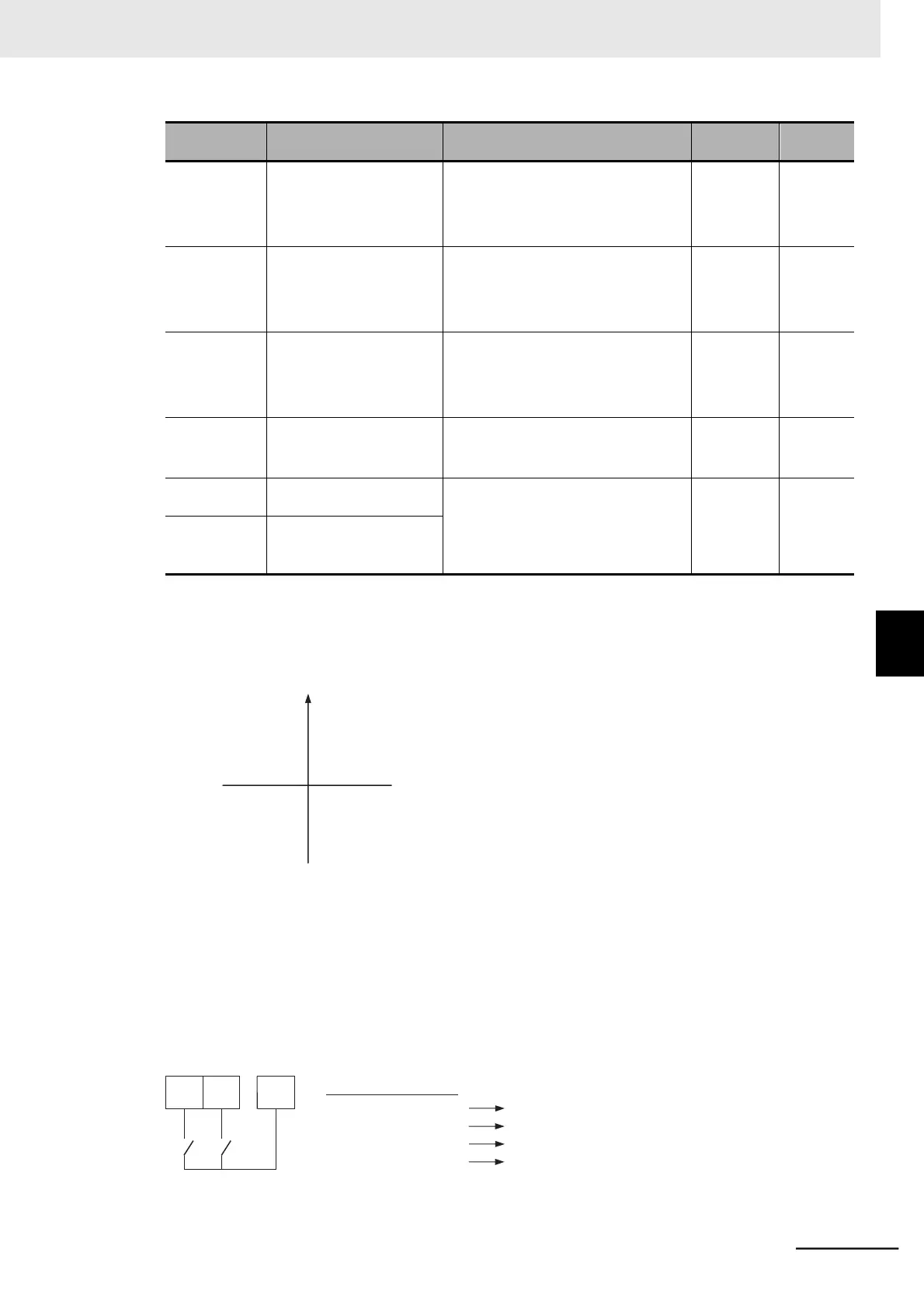
Details of Four-quadrant Separate Setting Mode (b040 = 00)
The following figure shows the Torque Limit 1 to 4 (b041 to b044) when the Torque Limit Selection
(b040) is set to 00 (Four-quadrant separate setting).
Torque
Reverse (RV ard (FW)
⚫
Details of Terminal Switching Mode (b040 = 01)
When the Torque Limit Selection (b040) is set to 01 (Terminal switching), the Torque Limit 1 to 4
(b041 to b044) switched by the torque limit switching 1 and 2 functions allocated to two of the
multi-function input terminals are defined as follows.
(Example) When torque limit switching 1 (TRQ1) and torque limit switching 2 (TRQ2) are allocated to
multi-function input terminals 6 and 7, respectively (C006 = 41, C007 = 42)
42 41
41: TRQ1 42: TRQ2
6-2 Torque Limit Function
6-2-1 Torque Limit Function Settings