6 Vector Control and Applied Functions
Multi-function Compact Inverter 3G3MX2-EV2 User’s Manual (I666-E1)
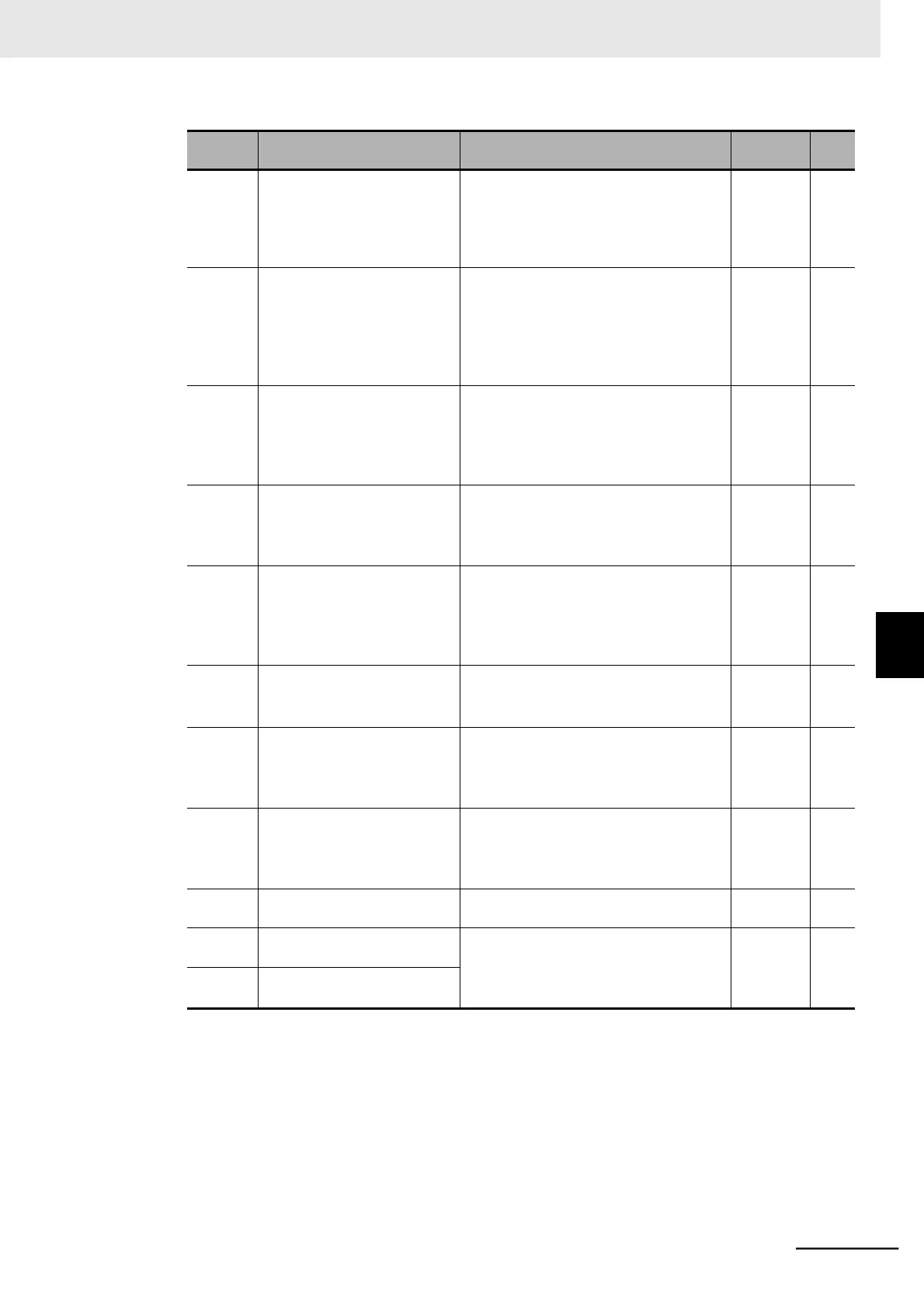
Brake Control Function
Selection
00: Disabled
01: Enabled (DC Injection Braking
enabled during stop)
02: Enabled (DC Injection Braking dis-
abled during stop)
0.00 to 5.00
The time from when the inverter reaches
the Brake Release Frequency until it out-
puts the brake release signal. Set the time
until the output current reaches the Brake
Release Current value.
Acceleration Wait Time on
Brake Control
0.00 to 5.00
Set the mechanical delay time from when
the brake confirmation signal (or brake
release signal) turns ON until the brake is
activated actually.
Stop Wait Time on Brake
Control
0.00 to 5.00
Set the mechanical delay time from when
the brake release signal turns OFF until
the brake is forced actually.
Brake Error Detection Time
0.00 to 5.00
Set this to equal to or longer than the time
until the brake confirmation signal turns
ON after the brake release signal is
output.
Brake Release Frequency
*1
0.00 to 590.00
Set the frequency at which the brake
release signal is output.
0.00 to 2.00 Rated current of inverter
Set an output current value sufficient
enough to support the load and output the
brake release signal.
Rated cur-
rent of
inverter
0.00 to 590.00
Set the frequency at which the brake
release signal turns OFF and forces the
brake during stop.
Multi-function Input 1 to 7
Selection
44: BOK (Brake confirmation)
Multi-function Output 11/12
Selection
19: BRK (Brake release)
20: BER (Brake error)
Multi-function Relay Output
(AL1, AL2) Function Selection
*1. Set this to a value larger than the Starting Frequency (b082).
*2. If the set value is too low, the inverter may not output a sufficient torque when the brake is released.
6-6 Brake Control Function
6-6-2 Brake Control Function Settings