6 Vector Control and Applied Functions
Multi-function Compact Inverter 3G3MX2-EV2 User’s Manual (I666-E1)
•
To provide an interval between each input to the Position command selection 1 to 3 terminals to pre-
vent false recognition, set the wait time until the inverter recognizes input to these terminals in the
Multi-step Speed/Position Determination Time (C169).
Be sure to set these parameters appropriately. Note that increasing the determination time setting
lowers the responsiveness.
Multi-step Position
Command 0
Position Limit Setting (Reverse Side) (P073) to
Position Limit Setting (Forward Side) (P072)
*1
(Displays upper 5 digits excluding “-”)
( 1 multiplication)
Multi-step Position
Command 1
Multi-step Position
Command 2
Multi-step Position
Command 3
Multi-step Position
Command 4
Multi-step Position
Command 5
Multi-step Position
Command 6
Multi-step Position
Command 7
Multi-function Input
Selection
66: CP1 (Position command selection 1)
67: CP2 (Position command selection 2)
68: CP3 (Position command selection 3)
Multi-step Speed/Posi-
tion Determination
Time
0 to 200 ( 10 ms)
Time until terminal input is recognized.
*1. The digit shift display mode can be used.
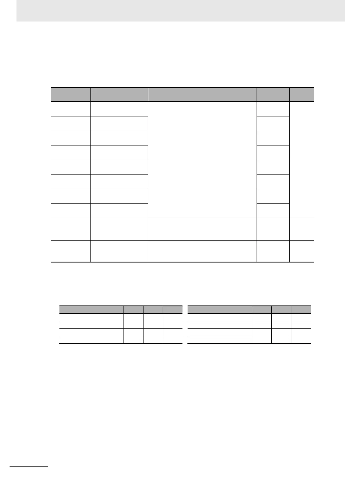
⚫
Relationship between Multi-step Position Command 0 to 7 and CP1 to CP3
(Position Command Selection 1 to 3)