6 Vector Control and Applied Functions
Multi-function Compact Inverter 3G3MX2-EV2 User’s Manual (I666-E1)
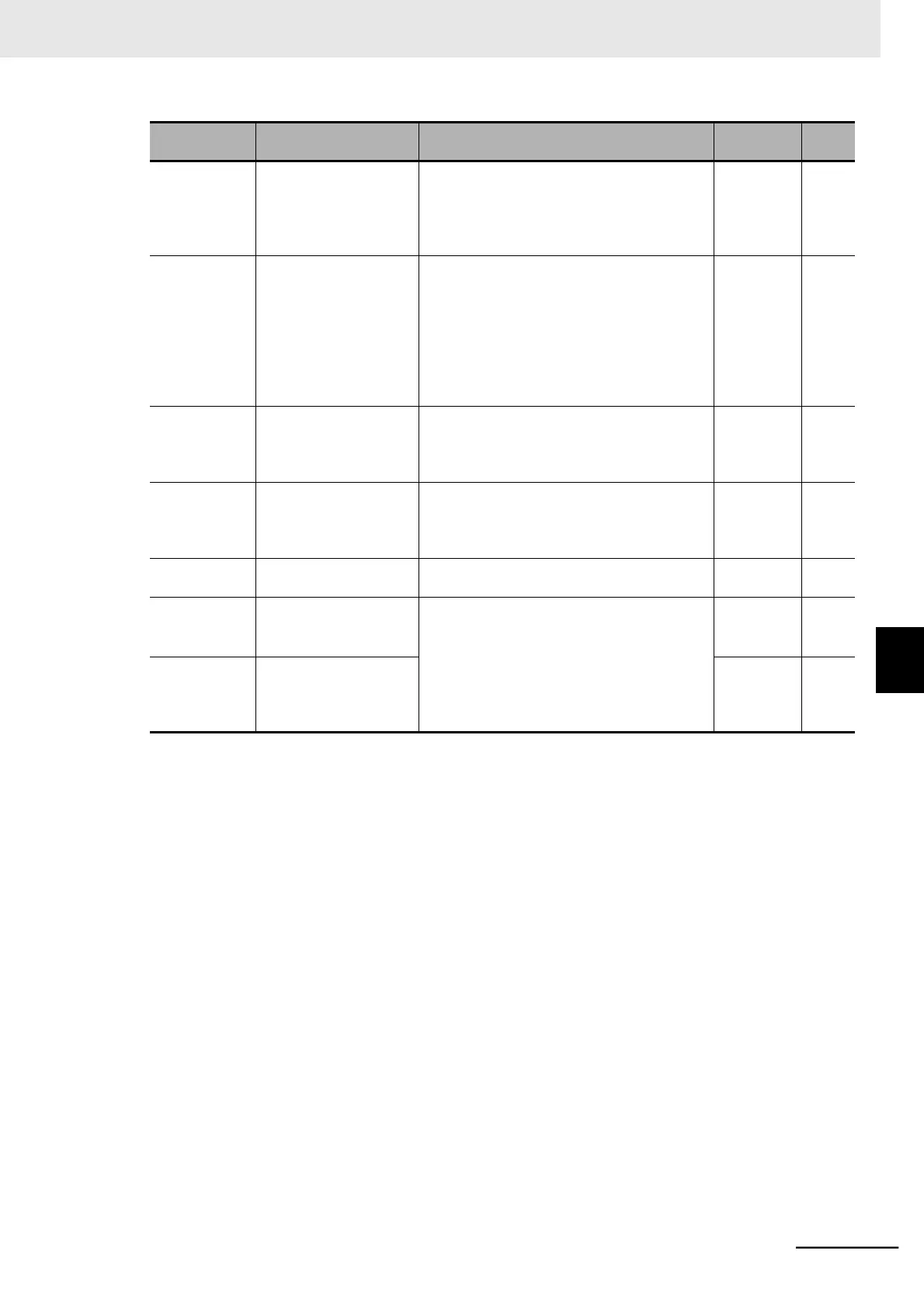
Acceleration Wait Time
on Brake Control
0.00 to 5.00
Set the mechanical delay time from when the
brake confirmation signal (or brake release
signal) turns ON until the brake is activated
actually.
Stop Wait Time on
Brake Control
0.00 to 5.00
Set the mechanical delay time from when the
brake release signal turns OFF until the brake
is forced actually.
The creep operation time or the stop wait
time, whichever is longer, takes priority. Set a
sufficient time that causes the brake to be
activated and applied without fail.
Brake Error Detection
Time
0.00 to 5.00
Set this to equal to or longer than the time
until the brake confirmation signal turns ON
after the brake release signal is output.
0.00 to 2.00 Rated current of inverter
Set an output current value sufficient enough
to support the load and output the brake
release signal.
Rated
current of
inverter
Multi-function Input 1
to 7 Selection
44: BOK (Brake confirmation)
Multi-function Output
11/12 Selection
19: BRK (Brake release)
20: BER (Brake error)
23: POK (Positioning ready)
Multi-function Relay
Output (AL1, AL2)
Func-
tion Selection
*1. If the creep speed setting is too low, the inverter may not be able to output a sufficient torque to keep the load
in position. Set such a frequency that enables the inverter to stably output a sufficient torque.
*2. DC injection braking is enabled when the interlock function with simple position control and brake control is
used. DC injection braking works even when the inverter is stopped to support its load holding capability. This
is effective, for example, to prevent fall accidents when the brake is forced.
*3. If the set value is too low, the inverter may not output a sufficient torque when the brake is released.
*4. The digit shift display mode can be used.
6-7 Simple Position Control
6-7-9 Interlock Function with Simple Position Control and Brake Control