*1. Setting the PID Selection (A071) to Enabled causes the analog input selection setting in A036 to be allocated
to the PID feedback function.
When the 1st Frequency Reference Selection (A001) is set to 01 (Control circuit terminal block), the analog
input setting other than that selected in A076 is used as the target frequency reference. In this case, the set-
ting in A005 and the function allocated to the terminal AT (Analog input switching) are disabled.
*2. Refer to 7-5-7 Frequency Calculation Function on page 7-39.
*3. In A079, you can set a target value, or have a setting that overlaps with the PID Feedback Selection value.
With an overlapping setting, the analog input is used for both the feedback and feedforward signals.
Precautions for Correct Use
•
When the PID function is enabled, the setting unit for the following parameters is changed to
percentage as 100% of the maximum frequency.
Note also that, these parameters are read or written via Modbus communication, the data
unit differs between read and write operations. Set parameter values in units of 0.01 Hz for
writing and in units of the following percentages as 100% of the maximum frequency for
reading.
F001: 0.01%
A011, A012, A020/A220, A021 to A035, A101, A102, A145: 0.1%
•
When using the PID function, do not set the Analog Input Filter (A016) to 31 (500-ms filter
with 0.1-Hz hysteresis). Doing so may result in unstable operation.
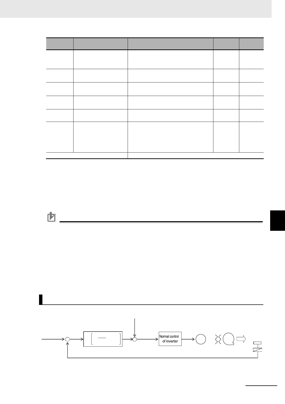
Kp: Proportional gain
(A072: PID P gain)
Ti: Integral time
(A073: PID I gain)
Td: Derivative time
(A074: PID D gain)
s: Operator