Multi-function Compact Inverter 3G3MX2-EV2 User’s Manual (I666-E1)
⚫
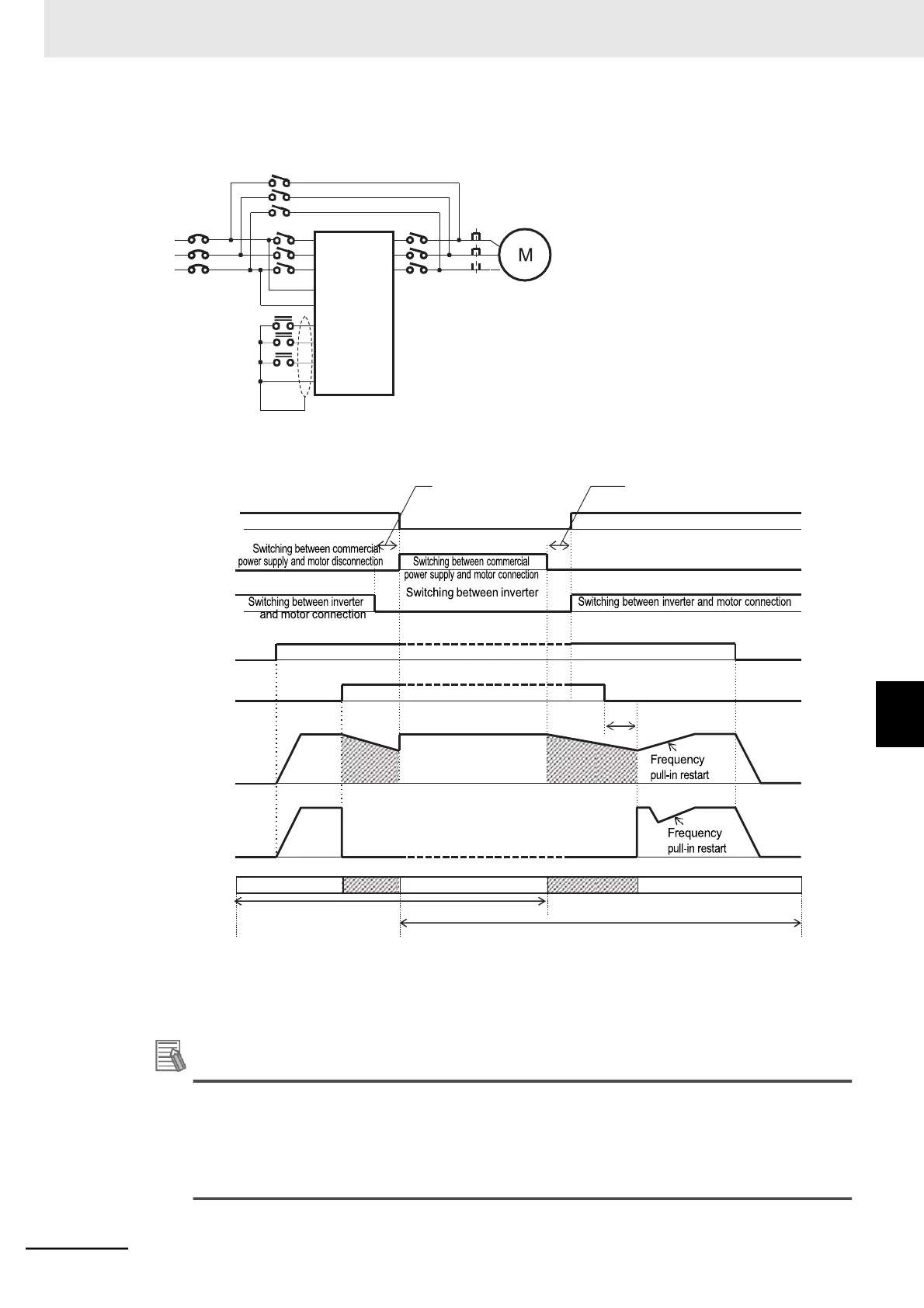
Connection diagram for commercial switching operation
MC2
⚫
Timing diagram for commercial switching
MC1
MC2
MC3
FW input
(FWY)
CS input
(CSY)
Motor
rotation speed
Output
frequency
Driven
by
commercial
power
supply
Switching
from
inverter
Operation
to
Co
mmercial
Power
Supply
Operation
Switching from Commercial Power Supply Operation to inverter Operation
•
Make sure that MC3 and MC2 are mechanically interlocked. Doing so may cause an inverter dam-
age.
Additional Information
•
For FWY, RVY, and CSY, use low-voltage relays according to your application.
•
If an overcurrent trip occurs during frequency pull-in restart, increase the Restart Standby
Time (b003).
•
The inverter can be set up to restart automatically at power-on. In this case, the terminal CS
is not required. For details, refer to 5-8-2 Restart after Resetting on page 5-44.
Interlock time for MC2 and
Inverter power supply ON
Inverter power supply OFF
Interlock time for MC2 and MC3
Switching between commercial power
supply and motor disconnection
7-5 Other Operation Functions
7-5-14 Commercial Switching (CS)