8 Communications Functions
Multi-function Compact Inverter 3G3MX2-EV2 User’s Manual (I666-E1)
A slave address is a serial number from 1 to 247 set in advance for each inverter (slave). (Only the
inverter that matches the slave address specified in the query will capture that query.)
⚫
Simultaneous broadcast to up to five groups
Set the slave address to 0 to perform broadcasting (simultaneous broadcast).
In a broadcast, all slaves receive data, but they return no response to it.
Moreover, during a broadcast, this inverter cannot perform data read or loop-back operation.
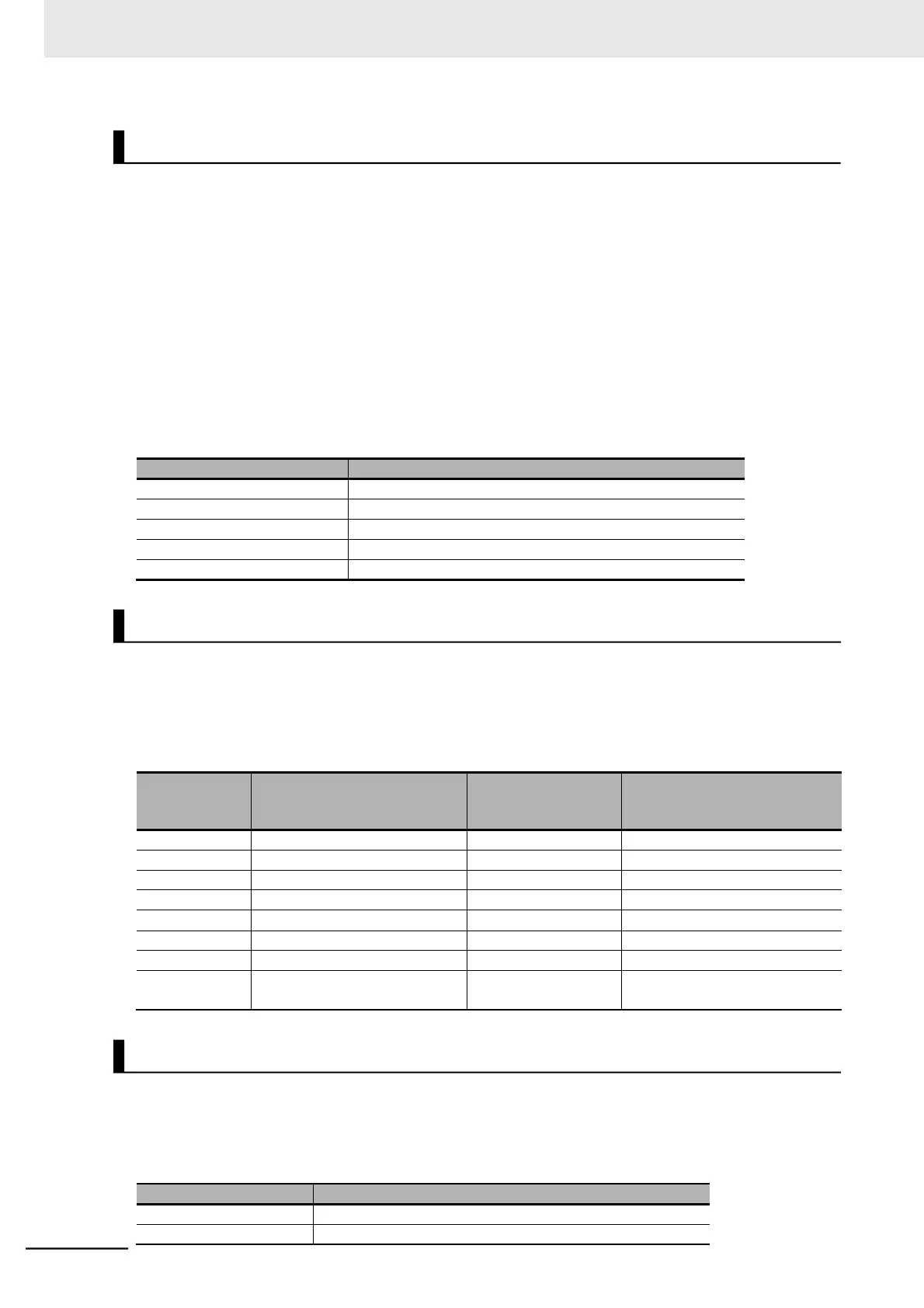
Although the Modbus specifications define the slave addresses between 1 to 247, using the slave
addresses 250 to 254 on the master side enables you to perform simultaneous broadcasting by
group. (In this case, the slaves return no response.)
Please note that this function is enabled for write commands (function code: 05 hex, 06 hex, 0F hex,
and 10 hex) only.
Simultaneous broadcast to slave addresses 01 to 09
Simultaneous broadcast to slave addresses 10 to 19
Simultaneous broadcast to slave addresses 20 to 29
Simultaneous broadcast to slave addresses 30 to 39
Simultaneous broadcast to slave addresses 40 to 247
A function code specifies the function to be performed by the target inverter(s).
The supported function codes are as shown in the table below.
⚫
Function code
Maximum number of
data bytes per
message
Maximum number of data per
message
Read from Holding Register
Write to Holding Register
Write to Multiple Holding Registers
Read/Write from/to Multiple
Holding Registers
32 each for read/write
operation
16 registers each for read/write
operation (in bytes)
A message sends data related the function code.
The data transmission format differs depending on the function code.
Among the data used in Modbus communication, the 3G3MX2 Series supports the following data types.
Binary data (1 bit) that supports read/write operation
16-bit data that supports read/write operation