Multi-function Compact Inverter 3G3MX2-EV2 User’s Manual (I666-E1)
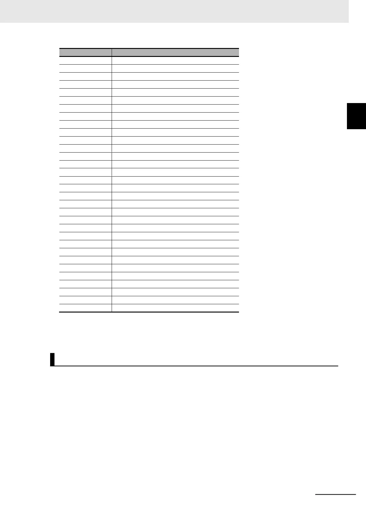
Multi-function Output 11 ON Delay Time
Multi-function Output 11 OFF Delay Time
Multi-function Output 12 ON Delay Time
Multi-function Output 12 OFF Delay Time
Multi-function Relay Output ON Delay Time
Multi-function Relay Output OFF Delay Time
Logic Output Signal 1 Selection 1
Logic Output Signal 1 Selection 2
Logic Output Signal 1 Operator Selection
Logic Output Signal 2 Selection 1
Logic Output Signal 2 Selection 2
Logic Output Signal 2 Operator Selection
Logic Output Signal 3 Selection 1
Logic Output Signal 3 Selection 2
Logic Output Signal 3 Operator Selection
Multi-function Input 1 Response Time
Multi-function Input 2 Response Time
Multi-function Input 3 Response Time
Multi-function Input 4 Response Time
Multi-function Input 5 Response Time
Multi-function Input 6 Response Time
Multi-function Input 7 Response Time
Multi-step Speed/Position Determination Time
Operation Selection on Option Error
Overspeed Error Detection Level
Speed Deviation Excessive Level
Pulse Train Frequency Scale
Pulse Train Frequency Filter Time Parameter
Pulse Train Frequency Bias Amount
Pulse Train Frequency Upper Limit
Pulse Train Frequency Lower Limit
For parameters for which you can change data during RUN, refer to the Changes during RUN column
of the tables in Section 4 Parameter List.
The 3G3MX2-E Series Inverter limits the parameters displayed on the Digital Operator to prevent
changes to parameters that are not displayed when the Display Selection (b037) is set to 04 (Basic
display).
The 3G3MX2-EV2 Series does not provide such a basic display capability.
Refer to 5-1-1 Display Selection on page 5-3 for information on the display selection.
1-5 Comparison with Previous
Model
1-3-2 External Dimensions
Deletion of Basic Display of the Display Selection