Chapter 2. Installation & Connection
2-2
2
Installation & Connection
2-1. Installation
Make sure that the radio wave conditions at the installation location are favorable before actually
installing the WE70 wireless unit.
■
Installation Location
Install this product as high as possible.
Do not install it to the following places:
• Where it is exposed to direct sunlight
• Where with extremely high humidity
• Near devices such as televisions, radios, and computers
• Near devices such as motor, drill, and welder
• Near strong magnets
• Near fluorescent lights
• Inside a metal panels or locations surrounded by metal or concrete
If WE70 is installed in a metal panel, be sure to mount the magnetic-base antenna outside the panel where
there are no obstacles.
■
Installation Precautions
●
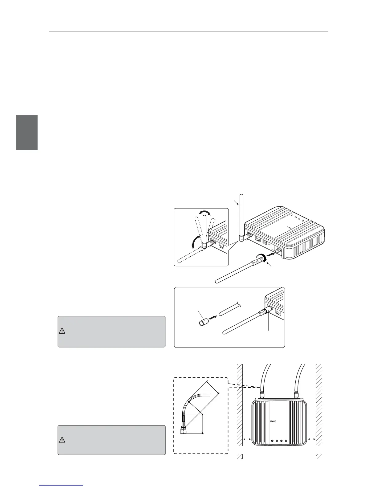
Mounting Antenna
A set of 2 antennas function as diversity
and is good at multi-path, allowing
communication under stable radio wave
status.To install, hold the connection point
of antenna and turn the antenna clockwise.
Antennas can be bent to an angle ranging
from 0 to 90 degrees. They can be turned
right and left while being bent.
To uninstall, hold the connection point of
antenna and turn the antenna
counterclockwise.
* To ensure performance, always connect both of 2
antennas.
* If radio wave status is bad, change a direction or
an installation location of an antenna.
* Use antenna connector cover to dust preven-
tion.(See right)
●
Installing the magnet base antenna
and antenna extension cable
Use the connector cover when connecting
a cable.
●
Margin and Spacing
For heat release, ensure space between
a wireless unit and a control panel or
other equipment as shown in the right.
Antennas manufactured by other
manufacturer cannot be used
because of the conflict with Technical
Standard Conformity Certification.
Caution
Do not grasp or pull the antenna
itself which is mounted to the
wireless unit.
Otherwise it may be damaged.
Caution