2-5
Chapter 2. Installation & Connection
2
Installation & Connection
■
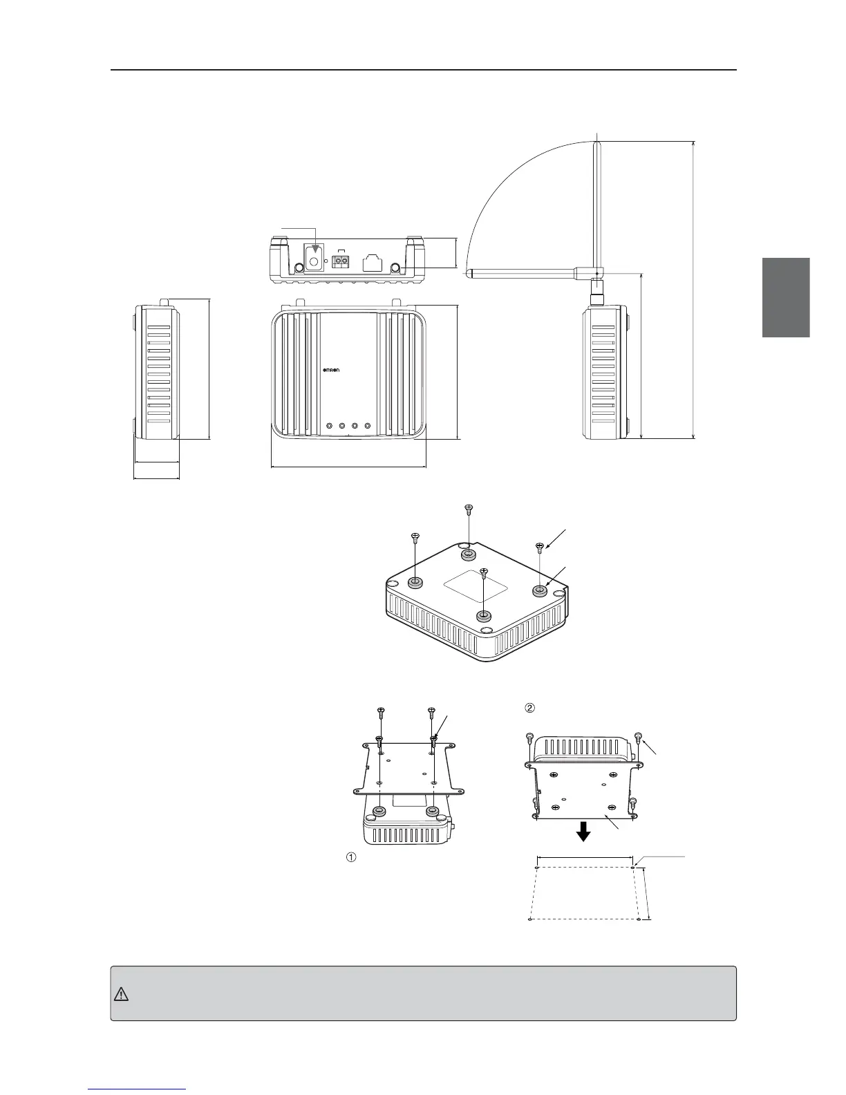
Dimensions (Common with WE70-AP/CL)
■
Installation Method
●
Mounting Magnets
Mounting magnets allows
temporary installation and easy
move for setup and testing before
actual operation.
Mount magnets using screws as
shown in the right.
For WE70-CL Only
ETHERNET
INIT
PUSH
RSSI
+–
24V
WE70-AP
LANMODE
FA WIRELESS LAN ACCESS POINT
POWER WIRELESS
120 ± 1.0
34.5 ± 0.5
36
103 ± 1.0
22.6
107.6 ± 1.0
(Unit: mm)
128.5
231.5
Mounting screws for this wireless
unit must be tightened with torque of
4.4 to 5.3in. lb. (0.5 to 0.6N.m)
Tighten using screws at the mounting holes
Flat-head screw
(Accessory)
Mounting Hole Dimensions
(unit mm)
108 ± 0.1
116 ± 0.1
4 – M5
Screw Mounting
Bracket (Accessory)
Tapping Screw
(Accessory)
Magnet (Accessory)
Flat-head screw (Accessory)
Mounting screws for this wireless unit
must be tightened with torque of 4.4 to
5.3in. lb. (0.5 to 0.6N.m)
●
To Mount Using Mounting
Bracket
Attach the mounting bracket on
accessory magnets which are
installed on a wireless unit.
Installation on a control panel
requires screw hole drilling.
Installation with magnets cannot be used at the location with excessive vibration. Use the mounting bracket or DIN
rail adapter in that case.
Caution