2-2. Connection
For connecting the antenna and the antenna extension cable, see “2-1 Installation” (P 2-1).
■
Wiring Precautions
• Signal lines and power lines must be separated to avoid influence of noise.
• Do not lay cables close to antennas.
• Wiring must be done while power is off.
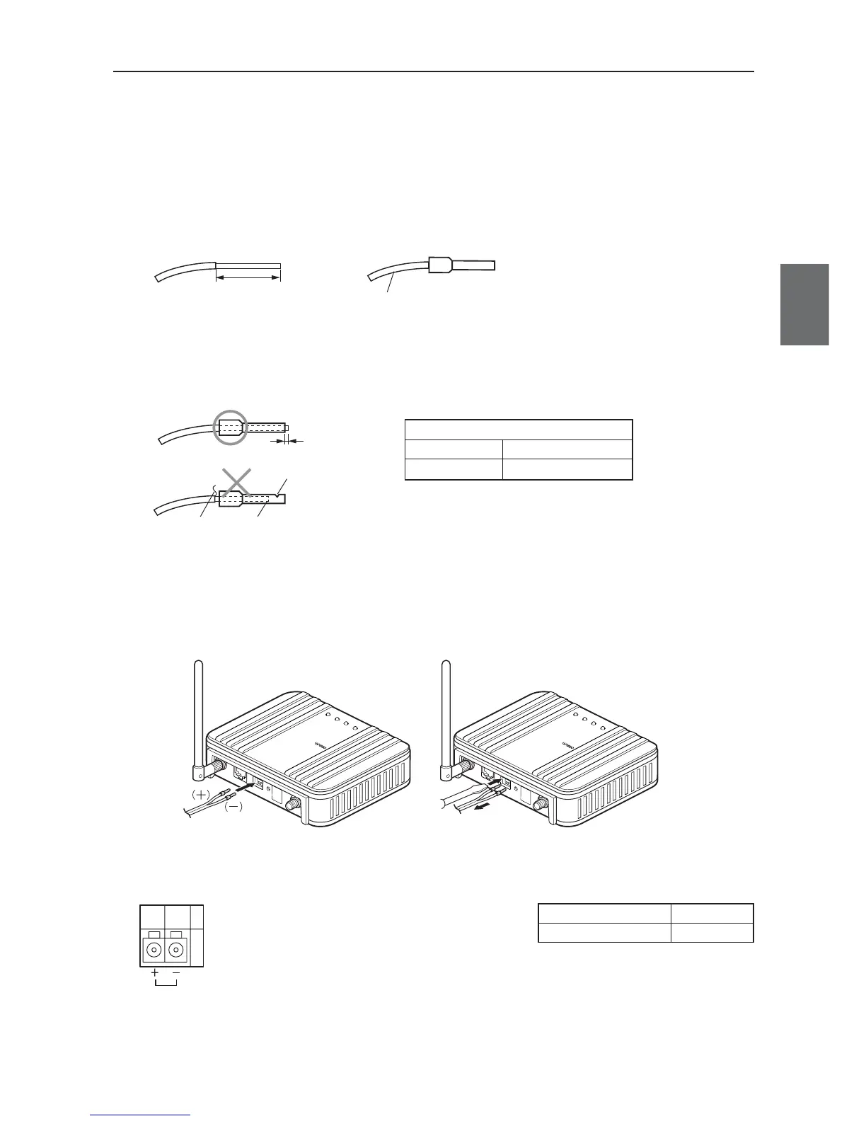
• Use a pin terminal or a cable for connection as shown below.
A pin terminal must be clamped with an appropriate tool based on its size.The tip of a wire must be cut in the
same length as the pin terminal or 0.5mm longer.A whisker must not exist, and a pin terminal must not be
broken.
• Plug the pin terminal into the power terminal block to the end.Fix wiring close to its connector so that a
cable should not apply load to the connector due to its twisting or weight.
• A pin terminal must be unplugged while inserting a flat-head screw driver as shown below.
■
Main Unit Power Wiring
Power of the wireless unit is 24VDC.
A wireless unit requires 24VDC power supply.
Use a power source of 15W or higher, taking
inrush current on startup into account.
Omron's switching power supply is recommended.
See "Option" of "Appendix", "Power Supply" (P.Appendix-3).
And, it power is supplied from the battery supply via the DC-DC converter.
• This unit needs to be installed under local regulations.
• This unit is intended to be supplied by a "Listing Class 2" or "L.P.S." and rated from 24V, 250mA.
2-7
Chapter 2. Installation & Connection
2
Installation & Connection
Line Voltage 24VDC
Allowable Voltage Range 20.4 to 26.4VDC
Phoenix Contact Inc.*
Pin terminal AWG18 AI 0.75-10
Clamping Tool CRIMPFOX ZA3