range Pi User Manual Copyright reserved by Shenzhen Xunlong Software Co., Ltd
108
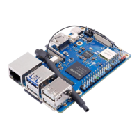
2) The corresponding relationship between GND, RXD and TXD pins of the debugging
serial port of the development board is shown in the figure below
3) The GND, TXD and RXD pins of the USB to TTL module need to be connected to
the debugging serial port of the development board through a DuPont line
a. Connect the GND of the USB to TTL module to the GND of the development
board
b. The RX of the USB to TTL module is connected to the TX of the development
board
c. The TX of the USB to TTL module is connected to the TX of the development
board
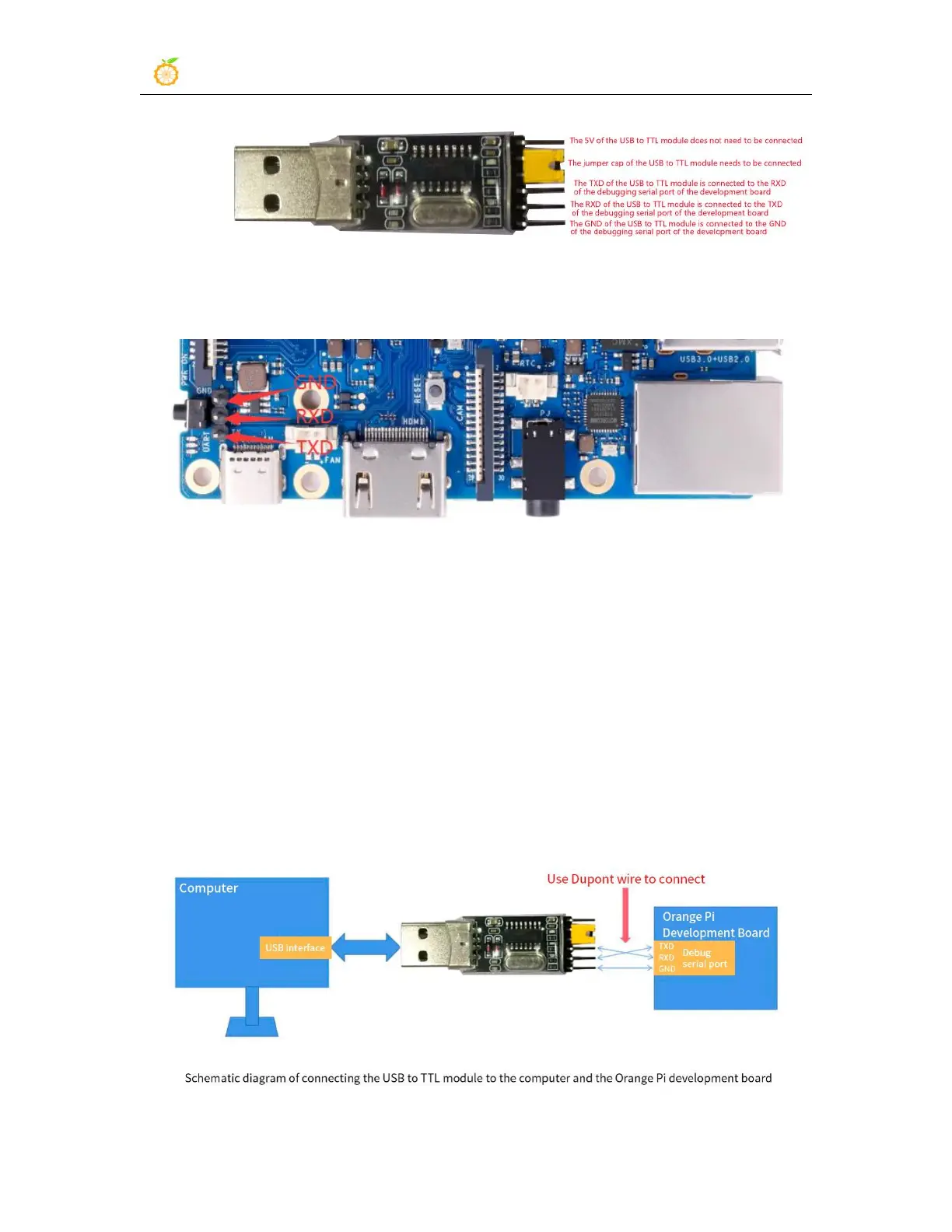
4) The schematic diagram of connecting the USB to TTL module to the computer and
the Orange Pi development board is as follows