13 - 43
Adjustment
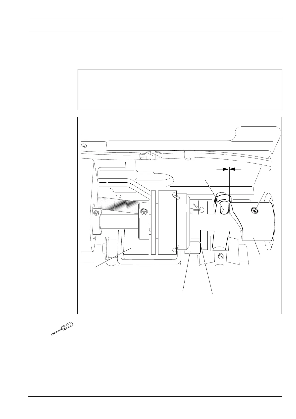
13.07 Adjusting the thread trimmer -900/81
13.07.01 Resting position of the roller lever / radial position of the control cam
Requirement
1. When the thread trimmer is in is resting position, lever 5 should be touching piston 6
and the roller of roller lever 7 should be 0.3 mm away from control cam 3.
2. When the take-up lever is at t.d.c., control cam 3 should just have placed roller lever 7
in its resting position.
● Having made sure that piston 6 is positioned against the left stop, adjust magnet 1 (2
screws) in accordance with requirement 1.
● Adjust control cam 3 (screws 4) in accordance with requirement 2.
Fig. 13 - 39
3
4
1
7
6
5
0,3 mm