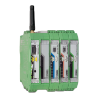
RAD-900-...
4/138
PHOENIX CONTACT 3827_en_B
8 PLC/Modbus RTU dual mode...................................................................................................93
8.1 Configuration via PSI-CONF software .................................................................94
8.2 Addressing I/O extension modules ......................................................................95
8.3 Watchdog ............................................................................................................95
9 Addressing I/O extension modules and RAD-900-DAIO6 with Modbus RTU ...........................97
9.1 Modbus function codes .......................................................................................97
9.2 Modbus protocol..................................................................................................97
9.3 Addressing registers............................................................................................98
9.4 Module type and error code register....................................................................99
9.4.1 Assigning I/O extension modules to the register ................................100
9.5 Modbus memory map........................................................................................100
9.5.1 RAD-AI4-IFS process data .................................................................101
9.5.2 RAD-PT100-4-IFS process data ........................................................102
9.5.3 RAD-AO4-IFS process data ...............................................................103
9.5.4 RAD-DI4-IFS process data ................................................................104
9.5.5 RAD-DI8-IFS process data ................................................................104
9.5.6 RAD-DOR4-IFS process data ............................................................106
9.5.7 RAD-DO8-IFS process data ...............................................................107
9.5.8 RAD-DAIO6-IFS and RAD-900-DAIO6 process data .........................108
9.5.9 Complete overview of the Modbus memory map ...............................109
9.6 Error codes and formats for analog input and output values..............................112
9.7 RSSI signal register ...........................................................................................113
10 Detecting and removing errors................................................................................................115
10.1 Loopback test during serial data transmission...................................................121
11 Diagnostics on the wireless module........................................................................................123
11.1 Diagnostic LEDs ................................................................................................123
11.2 LED bar graph ...................................................................................................125
11.3 Diagnostics via PSI-CONF software ..................................................................128
11.3.1 Recording parameters .......................................................................130

 Loading...